Re: HP-42S partial schematic
Message #19 Posted by Diego Diaz on 10 Nov 2009, 12:02 a.m.,
in response to message #16 by Lyuka
Hi Lyuka, all...
Excelent job! (to say the least) :-)
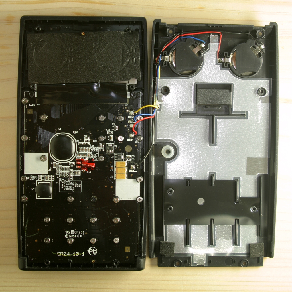
One thing that calls my attention was the numbering order of the Saturn CPU pins. After looking at your pictures I realized that the plastic protective frame aroud it has a number "1" stamped in the location you choose to start numbering.
However a closer look to the PCB denotes the "PIN 1" indicator dot just in the corner between VSS and VDD (probably not visible in the pictures but I remember that since I removed said protective frame in the unit I took the schematic from... ;-)
Also some of the not-connected pins are tied together on the PCB... certainly this is irrelevant for technical use; just for the sake of accuracy.
Again my congrats for a nice and clean work.
Regarding the question on the keyboard contact resistance. This is just a design characteristic of the keyboard construction itself and not a functional requirement.
The Pioneer's KB is made of carbon traces, this causes some resistance to be present when a key is pressed; but a clean contact (0 Ohms) is also perfect for operation.
One of the most annoying troubles with heavily used Pionners is the referred CPU lock-up due to carbon dust between frequently used key contacts. Dissasembling, cleaning and reassembling the keyboard is, though possible, not trivial.
Hope this helps.
Best from the middle of the Atlantic Ocean.
Diego.
| 
