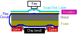
For the 30 series, HP designed an entirely new way of assembling their calculators. Behind the keyboard was a thick sheet of metal. On the back of this sheet was a foam pad and a single flexible circuit was wrapped around the metal/foam board. In front, an insulating sheet with holes for key contacts was placed over the flexible circuit and a snap disk contact sheet was placed over that and spot welded into place. (The welds made contact between the snap disk contact traces and the main flexible circuit.)
The flexible circuit wrapped around the metal and was attached to the foam in back. A hard plastic backbone held the chips in place on the flexible circuit with the foam supplying pressure against the circuit under the chip leads. The chips were NOT soldered to the circuit!

This arrangement was quite easy to assemble and also gave the 30 series keyboard a level of rigidity even greater than that of the 20 series while still making keyboard repairs easy as on the Classic series. (The 20 series heatstaking made keyboard repairs difficult.)
![]() Picture of the back of the main board showing the flexible circuit over foam. To the left is the empty spine with the circuit side up. (~40K)
Picture of the back of the main board showing the flexible circuit over foam. To the left is the empty spine with the circuit side up. (~40K)
![]() Picture of the front of the main board showing the flexible circuit key pads over metal, with the snap disk layer on top. To the left is the empty spine with the circuit side down. (~38K)
Picture of the front of the main board showing the flexible circuit key pads over metal, with the snap disk layer on top. To the left is the empty spine with the circuit side down. (~38K)
Unfortunately, the original design didn't measure up to the reliability of earlier HP calculators so HP redesigned the 30 series interior. The redesigned models used a more conventional design with a single rigid circuit board with snap disks on one side and ICs soldered in place on the other side. A plastic spine provided extra rigidity but didn't hold the chips in place as on the earlier version. These later models weigh about 1.5 oz less due to the removal of the metal sheet.
![]() Picture comparing early (flex circuit) and late (rigid circuit) series 30 calculators. On the older model (left) the spine actually held the chips in place. In the later model, the chips were soldered in place. Also note the metal retainers along the sides of the early version which were essential to providing sufficient pressure on the chip leads. (~80K)
Picture comparing early (flex circuit) and late (rigid circuit) series 30 calculators. On the older model (left) the spine actually held the chips in place. In the later model, the chips were soldered in place. Also note the metal retainers along the sides of the early version which were essential to providing sufficient pressure on the chip leads. (~80K)
![]() Picture of the front of the new main board showing the integrated snap disks. (~45K)
Picture of the front of the new main board showing the integrated snap disks. (~45K)
Information on the register layout and programming model may be found on the CPU and programming page.
The 30 series improved the display by increasing the digit size and adding commas. In addition, the display was angled to be more readable on a desktop.
The 30 series returned to using a separate battery and battery door. The curator considers this a shame as the 20 series pack seemed so clever. Collectors are often annoyed to find 30 series models without battery doors because without a battery in place, the doors fall off rather easily. Another flexible circuit was used to connect the battery terminals to the calculator circuitry. A "Bright Metal Alloy" replaced gold for contacts.