HP Articles Forum
[Return to the Index ]
[ Previous | Next ]
Repairing the hp 82104A Card Reader
Posted by Dave the "lostrabbit" on 25 May 2000, 12:05 p.m.
Pictures by Ty Rogers
Many of us these days with the 82104A card readers for the hp 41 series of calculators have been having problems with the driven gear roller becoming "gooey" and therefore rendering our beloved readers inoperable. I have repaired quite a few of these, and now I have decided to publish my procedures here so that you, the do-it-yourself type, can repair yours.
The tools you will need include:
A very small philips head screwdriver
A not quite as small philips head screwdriver
A curved pair of hemostats
An x-acto or utility knife
Several cotton swabs
A bottle of isopropyl alcohol (NOT beer!)
Material for the repair: either a small piece of model airplane fuel line (the pink tubing with the small inside diameter OR a pair of O rings, somebody else has stated that they are size 006, dimensions are 2.9mm OD, 1.78 ID.UPDATE! I have yet to find a "size 006" O ring, the ones that I have used are english measure 1/4" OD, 1/8" ID, which works out to be something like 6.35mm OD and 3.18mm ID.
Now that the label is off, you now see three screws. Direct your attention at this point to the front of the reader, where it fits into the calculator. Here you will find 4 very small screws. Remove the 2 lower screws, one on each side, and put them in a safe place........an empty plastic pin box works well.
Now back to the 3 screws under the label. The one you want to remove is the one at the rear of the reader. The other 2 hold the drive slot assembly to the bottom half of the unit, and you aren't ready to remove those yet. Having gone this far, you should be able to lift the top half of the unit off the bottom half. Do this over the table as things may fall out! Work it, a little at a time and you will get it. Note the way the latches are assembled, make a sketch if you need to.
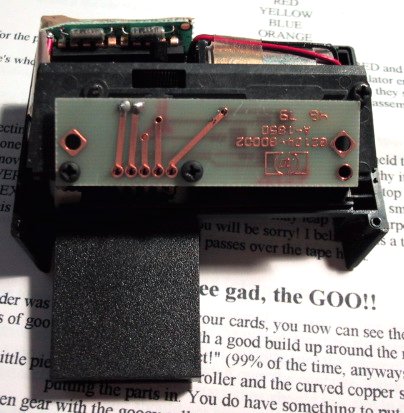
Picture of the opened card reader
Next, we want to remove the drive slot assembly from the lower half of the unit. First, I like to remove the 3 screws that hold down the circuit board to the slot assembly. Be VERY careful here as once you remove these, the circuit board will come off the vertical pins that make the contact and you will find a pair of long copper strips shaped like a fork below it. Do not bend these! Remove the last pair of screws that were under the label. Now the assembly is loose.
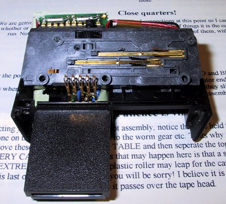
Picture showing drive slot assembly
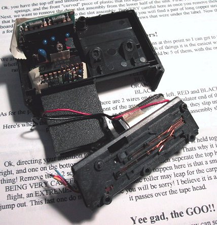
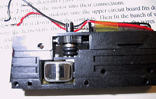
Picture showing drive assembly removed
As for the power supply to the motor, there are 2 wires on the far left, RED and BLACK; NOTE that the RED wire is closest to the front of the assembly, i.e. the calculator end of the unit.
Here's where the hemostats come handy, as the wires are a "friction" fit, they slip into the connections. Carefully pull each wire out with the hemostats and the drive slot assembly should be free.
Remove these 2 screws OVER THE TABLE and then separate the top half of the drive slot from the bottom BEING VERY CAREFUL!! A few things that may happen here is that a small curved piece of copper may take flight, an EXTREMELY SMALL white plastic roller may leap for the carpet, or another small copper strip may jump out. This last one do not bend or else you will be sorry! I believe it is a type of spring to hold the card down as it passes over the tape head.
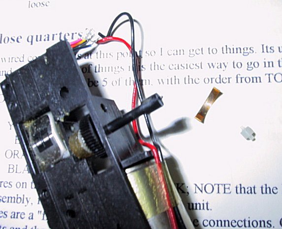
Picture showing read/write head and original wheel
Ok, put all those little pieces; the TINY white roller and the curved copper strip in your pinbox or whatever you are putting the parts in. You do have something to put them in, right?
To remove the driven gear with the gooey roller, use the hemostats. You will find a plastic pin with a slot in the end of it that looks like you need a screwdriver to remove it. But you don't! It is a friction fit, and a little twisting action as you pull with the hemostats will remove it. The pin is out, the driven gear with the gooey roller will now come out of the assembly through the top. Put the pin and the gear in your storage place be it the pinbox or whatever for now.
Now to clean. Use cotton swabs and the alcohol to clean the goo. Get it all. Use quite a few and make sure ANYTHING and EVERYTHING with goo has been cleaned. Be VERY CAREFUL around the tape head, in fact I like to clean that part last with fresh swabs and alcohol, kind of like cleaning a cassette deck back in the 80's. HA! Clean the little white roller as it will be gooey also.
Lets direct our attention to the driven gear, the one with the gooey roller. You need to clean off the goo, and there you will find an aluminum shoulder. Having made the decision whether to use the fuel line or the O rings it is now time to fix the problem gear. If you use the fuel line, slip it on then cut it off, chamfer the outer edge ever so slightly as to keep it from binding. It is not hard to do, just be patient with it. The O rings I do admit after jousting with Steve, offer an easy way to go. I dismantled one of the ones I had previously repaired with the fuel line and tried the O ring method. It works fine, although I could not detect (from the sound of the reader in operation) any benefit on the mechanicals.
Picture showing read/write head with o-rings
If your gear is not totally gooey, the stuff will be tough to come off. Use the knife and get it all off. Apply the material of your choice and we are ready to go back together. The gear is clean, right?
A few things I should point out beforehand. Check the condition of the worm gear on the motor. If you have goo there, clean it with a swab and the alcohol. Get it as clean as you can. Also, I like to check the fit of the worm gear on the shaft by touching the power supply wires to a single N cell battery and then while the motor is running apply a touch of the finger to insure it stalls. If it is slipping apply a touch of cyanocrylate glue (crazy glue) to the shaft making sure it doesn't run down into the motor! Also, apply lots of alcohol via the swab to the end of the worm gear where it fits into the plastic housing, i.e. the bearing area. There is more than likely goo here also.
Put the small white roller from whence it came back in its place in the top half of the slot assembly. Place the curved copper strip in its place in the bottom half. Now, very carefully attempt to put the top half of the drive slot onto the bottom half. A good approach is to hold both on edge and then fit them together using the locating dowel pins at each end. Beware the fact that things may fall out, especially the tiny roller, and that the copper strips must fit in the right places! It may take a few attempts to get this part right, but be patient! It will come together. Holding the two parts together replace the 2 screws that you removed a long time ago. One at top right, one at lower left on the underside.
Be careful with the spring contacts, the fork shaped ones. Again, do not bend these!
Having that part re assembled, put the circuit board that makes the contact with the fork shaped springs back on top. I like to start all of the 3 screws then tighten down the center one first, then the outer 2. Not real tight!
Next, place the drive slot assembly in its position, making sure the upper circuit board fits down and over the gold vertical contacts. Line up the holes, and fit it down over the contacts. Then fit the bunch of wires on the left side to their respective connections. Using the hemostats, they should just slip in nicely. the wires are tinned with solder, and should not become frayed if you are careful.
Replace the 2 screws that were under the label that hold the drive slot assembly into place.
IT WORKS!!!! YIPPEE!!!!
Put the card reader assembly aside, and reach for the top piece, the latches and their respective springs( the strips of metal). Note that one of these strips has a plastic or tape kind of coating, usually yellow but sometimes white. It goes on the LEFT so as to not short the components.
Now, holding the top in your hand, put the latches with the spring plates into position. The springs fit behind the vertical metal strip that the very small screws go through.
Now, holding the top with the latches and spring plates together in one hand, put the card reader assembly in your other hand and fit the top down over the bottom. Align the latches so their pins fit into the holes of the top and bottom halves. Get it together, but not quite all the way. The spring plates should be swinging in the breeze right now, that's how they should be.
Last step, get the curved piece of plastic and noting that it has a couple of tabs on the inside that the spring plates fit between, very carefully fit it between the latches and nearing position, fit the bottom of it into place making sure the spring plates fit between these tabs, then push forward with the plastic piece and fit it in at the top. this usually takes a few attempts, but I really do think it is the way to fly!
Replace the long screw at the bottom where the label was, and the 2 very small screws at the calculator end, apply the label and you are done!
Dave, aka "the rabbit"