HP Articles Forum
[Return to the Index ]
[ Previous | Next ]
Repairing an HP-41CX
Posted by Stefan Vorkoetter on 2 Apr 2000, 9:20 p.m.
Recently, my HP-42S broke down (the "9" key stopped working) and I found to my horror that there was no way to disassemble the calculator. I e-mailed all my colleagues to see if any of them had any old HP calculators lying around, and one of them did. He gave me his old (broken) HP-19C and HP-41CX.
The 19C was fairly easy to repair. It just needed a new battery pack, and the keyboard had become unplugged from the CPU board. There were also a few other minor repairs to make.
The 41CX was more challenging, but first a bit of history.
Long ago, I had an HP-41CV and one day it stopped working. I found that the CPU board is connected to the keyboard by a set of flexible connectors which rely on pressure to maintain contact. This pressure is provided by the screws that hold the calculator together, but the plastic posts that the screws go into had cracked (interestingly enough, my Braun shaver suffered the same failure on the very same day). A similar arrangement connects the module back-plane and battery connectors to the keyboard circuit. The repair consisted of a few drops of cyanoacrylate glue, and a wrap of fine wire around the posts until the glue had thoroughly set.Unfortunately, a few months later, I sold the calculator since I thought I might like one of those nifty BASIC-language pocket computers better. I was wrong, so the following year my wife got me an HP-42S for Christmas. It didn't have that same air of quality that the 41CV had, but it worked fine, and I'd been using it for about 10 years now... until the "9" key stopped working.
My colleague's HP-41CX was in need of more extensive repairs than my 41CV had needed. Here's a brief list of what was wrong:
On a positive note, the calculator did come with a number of useful things:
In this article, I will describe the steps I took to restore the calculator to working order. I will assume you have at least hobbyist-level skills in electronic equipment repair. I'm not an EE by any stretch of the imagination, but I've been tinkering with electronics since I was a little kid, so I don't mind taking things apart to try and fix them.
This information is provided as-is, with no warranty of any kind. Under no circumstances will Stefan Vorkoetter or the Museum of HP Calculators be liable for any loss or damage resulting from use of this information. If you attempt to repair your calculator using this information, you do so at your own risk.
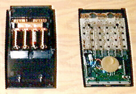 This photo shows the two halves of the HP-41CX case.
On the left is the back of the case. At the top are the module ports. The orange colored thing is the backplane, which connects the keyboard circuit board to the module ports, and also to the battery. Just below this you can see the battery, consisting of four size N alkaline cells. Near the bottom of the back are the holes through which the bottom screws pass.
On the right is the top of the case. At the top is the LCD, and the two dark circles on the back of it are the LCD driver chips. Below that and extending all the way to the bottom is the keyboard, held to the case by black plastic heat stakes. Also at the bottom is the CPU board, which is connected to the keyboard by flexible interconnects, aligned with the keyboard by the bottom screw posts, and held in place by the back of the calculator. The big yellow circle on the CPU board is the speaker (used by the BEEP and TONE functions, and the alarms).
In addition to the front and back case pieces, there's a 1/4 inch thick bezel which goes between the two case halves (from the outside of the calculator, it's the shiny band between the top and bottom matte finished case halves).
To disassemble the calculator, lay it face down on a soft surface and remove the battery. Peel the rubber feet off the back to expose the screws. Undo the four screws, and lift the back case off of the front. Then lift off the bezel, being careful to note its orientation.
Next, lift off the CPU board, and the black plastic insulator sheet (note its orientation; it has a notch cut out of one side). Removing the CPU board will expose the CPU to keyboard interconnects, and the black plastic frame that holds them in place (this might be slightly different in the 41C and 41CV models).
 I suspect this problem must be common to lots of HP-41
series calculators. The screw posts are under a great deal of stress, since
they must hold the machine tightly together. Any jolts received by
the calculator take their toll on the screw posts. Over time, they're bound
to weaken and crack.
I suspect this problem must be common to lots of HP-41
series calculators. The screw posts are under a great deal of stress, since
they must hold the machine tightly together. Any jolts received by
the calculator take their toll on the screw posts. Over time, they're bound
to weaken and crack.
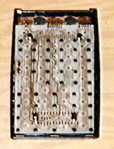
There are four screw posts in the HP-41, two near the bottom and two just above the battery hatch. These are visible in the photo at right, which is of the front case and keyboard, with the CPU board removed. The two bottom screw posts are in the second row of black dots from the bottom, and the two top ones are just above the topmost row of black dots (the black dots are heat stakes that hold the keyboard to the front case).
Notice the two rows of contact fingers between the top screw posts, and the two long rows and one short row between the bottom screw posts. (I think the 41C and 41CV don't have the short interconnect.)
Repairing cracked posts is fairly simple. First disassemble the machine and remove the CPU board. Also remove the three flexible interconnects, and the plastic frame that holds them in place (be careful not to crack the frame).
Apply a drop of thin cyanoacrylate adhesive (or liquid styrene solvent) into the cracks, and quickly tightly wrap each post with several turns of fine single-strand wire (I use 30 gauge wire-wrap wire, stripped of its insulation). Twist the ends of the wire to keep it from unwrapping. When the glue has set thoroughly (a few minutes for cyanoacrylate, or overnight for styrene solvent), unwrap the bottom posts. The top posts can remain wrapped since nothing has to fit over them. Apply some cyanoacrylate to the wire around the top posts and trim off any excess wire.
If cracked posts were the only things wrong with your HP-41, you can now reassemble it. Reinstall the frame and flexible interconnects and slide the CPU board back over the posts. Place the black plastic insulator sheet over the keyboard. Put the bezel on the front half of the case (note that the bezel is slightly narrower on one side than the other; the narrow side faces the front of the case). Place the back case onto the bezel, and screw everything back together (the short screws go in the bottom holes). Tighten the screws securely, but do not overtighten them. Reinstall the battery pack and turn it on. If all is now well, the calculator will display "MEMORY LOST".
On my HP-41CX, one of the three flexible CPU board to keyboard interconnects
was missing. It was most likely lost during a previous repair attempt (the
rubber feet were also missing). I decided to do away with the interconnects
entirely, and hardwire the CPU board to the keyboard. This has the advantage
that the connection will no longer rely on the integrity of the bottom screw
posts.
 The first
step is to mount the calculator to a convenient surface, and then mount the
CPU board next to it so that the wiring can be carried out. Here, I've taped
them both to a board. Overlap the CPU board on the bottom of the calculator,
component side down, as shown. Be sure to orient the board correctly.
The first
step is to mount the calculator to a convenient surface, and then mount the
CPU board next to it so that the wiring can be carried out. Here, I've taped
them both to a board. Overlap the CPU board on the bottom of the calculator,
component side down, as shown. Be sure to orient the board correctly.
Start by tinning all the conacts on the keyboard and CPU board using a fine-tipped soldering iron.
Cut 16 pieces of 30-gauge wirewrap wire to the appropriate length to reach
from the bottommost contacts on the keyboard to the corresponding contacts
on the CPU board. Strip 1/8" of insulation from each end of each piece, and
solder the 16 wires between the appropriate contacts as shown.
 Next, cut
4 pieces of wire of the appropriate length to reach from the middle
row of contacts on the keyboard to the corresponding contacts on the CPU
board. Strip 1/8" insulation from each end, and solder them in place as
shown.
Next, cut
4 pieces of wire of the appropriate length to reach from the middle
row of contacts on the keyboard to the corresponding contacts on the CPU
board. Strip 1/8" insulation from each end, and solder them in place as
shown.
 Now it's
time to move on to the final row. Cut 14 pieces of the appropriate length
to reach from the top row of contacts on the keyboard to the corresponding
rows on the CPU board. Strip 1/8" insulation from each end, and install them,
omitting the two locations that are blocked by the screw posts.
Now it's
time to move on to the final row. Cut 14 pieces of the appropriate length
to reach from the top row of contacts on the keyboard to the corresponding
rows on the CPU board. Strip 1/8" insulation from each end, and install them,
omitting the two locations that are blocked by the screw posts.
Cut two additional pieces about 1/4" longer to to connect the remaining two
pairs of pads. Route these wires around the screw posts (and the screw post
holes in the CPU board), and solder them in place.
 The next
step is to reinstall the CPU board on the keyboard. Before doing this, cut
a piece of electrical tape to the same length as the CPU interconnect frame
that you removed, and punch two holes in it to clear the screw posts. Also
glue some 1/8" thick foam rubber to the keyboard circuit board at the two
ends of the tape to hold the CPU board away from the keyboard once it's
reassembled.
The next
step is to reinstall the CPU board on the keyboard. Before doing this, cut
a piece of electrical tape to the same length as the CPU interconnect frame
that you removed, and punch two holes in it to clear the screw posts. Also
glue some 1/8" thick foam rubber to the keyboard circuit board at the two
ends of the tape to hold the CPU board away from the keyboard once it's
reassembled.
In the photo, the electrical tape is red, and the foam rubber is the two
black strips above and below the taped area.
 Finally,
carefully fold the CPU board onto the keyboard, lining it up with the posts.
It helps to lay a narrow metal ruler over the wires at the place where they
will bend (half way between the corresponding sets of pads) to get them all
to bend in the same place. Push the CPU board down over the screw posts until
it is sitting on the foam rubber, parallel to the keyboard. The photo at
right shows the CPU board in position. The photo below shows a side view,
with all the wires (blue) visible. You can also see the foam rubber strips
on which the CPU board is resting.
Finally,
carefully fold the CPU board onto the keyboard, lining it up with the posts.
It helps to lay a narrow metal ruler over the wires at the place where they
will bend (half way between the corresponding sets of pads) to get them all
to bend in the same place. Push the CPU board down over the screw posts until
it is sitting on the foam rubber, parallel to the keyboard. The photo at
right shows the CPU board in position. The photo below shows a side view,
with all the wires (blue) visible. You can also see the foam rubber strips
on which the CPU board is resting.
 At this point,
if there's nothing else to repair, you can reassemble your HP-41 as described
in the previous section. You might have to trim a half inch or so off the
bottom of the plastic insulator sheet to clear your foam rubber strips. You
may also find it a bit harder to tighten the bottom screws because the wiring
and foam padding might provide some resistance, but they will give. Just
be careful when tightening not to strip or crack the screw posts.
At this point,
if there's nothing else to repair, you can reassemble your HP-41 as described
in the previous section. You might have to trim a half inch or so off the
bottom of the plastic insulator sheet to clear your foam rubber strips. You
may also find it a bit harder to tighten the bottom screws because the wiring
and foam padding might provide some resistance, but they will give. Just
be careful when tightening not to strip or crack the screw posts.
My HP-41CX had badly corroded battery contacts because the last set of cells had been left in it for several years. Sanding the contacts merely got right down to the plastic under the contacts.
There are four battery contacts. When viewed from the back of the calculator, with the module ports at the top, the leftmost contact is the negative one. The rightmost is positive. The two in between aren't connected to anything except each other, and are just used to connect the two middle cells to one another when the battery pack is in place. The battery contacts are part of the module port back-plane, and the whole assembly is just a friction fit into the back of the case. It's fairly easy to pull out to work on it.
 I cut out
a 1/8" wide strip of thin brass strip (available at any hobby shop) wide
enough to span the two middle contacts, and glued it across them with
cyanoacrylate. This strip now serves to connect the two middle cells.
I cut out
a 1/8" wide strip of thin brass strip (available at any hobby shop) wide
enough to span the two middle contacts, and glued it across them with
cyanoacrylate. This strip now serves to connect the two middle cells.
For the positive and negative contacts, I was able to expose some uncorroded copper on either side of the center of the contact. I cut two more brass strips, each the width of a contact, and carefully soldered them to the clean copper on either side of center, effectively making a new contact.
The photo at right shows the end result. It's a bit fuzzy, but if you compare it to the back-plane from your calculator, you can see that the middle two battery contacts have been bridged, and that new contacts have been soldered onto the outer two.
To solder the new contacts in place, first tin the copper areas and apply a small amount of solder. Then tin the back side of the brass strip. Hold the strip in place against one side of a contact, and touch the soldering iron to the front side of the strip. The iron will heat the strip, and the solder behind it, and fasten it to the tinned copper area. Do the same with the other end of the strip. You have to do all this quickly, or you risk melting the plastic backing of the battery contacts.
When reassembling the calculator, clean the back-plane contacts that connect to the keyboard with some rubbing alcohol. Chances are they will have been contaminated with finger prints and solder flux while you were repairing the battery contacts.
 After several
hours spent repairing the 41CX, I put it all back together, installed the
battery, and was greeted by a "MEMORY LOST" message. A quick test
revealed that everything was working.
After several
hours spent repairing the 41CX, I put it all back together, installed the
battery, and was greeted by a "MEMORY LOST" message. A quick test
revealed that everything was working.
I also tested the card reader that came with the calculator. It seems to work most of the time, although it sometimes makes funny noises and gives an error message while reading. I intend to open it up and see what's wrong in the near future.
I then proceeded to give the machine a thorough cleaning. I used a very slightly dampened rag to clean all the keys, and the spaces between them. After a few minutes, I had a good-as-new HP-41CX. In some ways, it's actually better than new, since it no longer relies on pressure to maintain the critical keyboard to CPU interconnection.
 There are
still a few things that need to be fixed. The cover for the charging jack
is missing (although the calculator didn't come with a rechargeable battery).
One of the port covers is missing (the card reader was plugged into it when
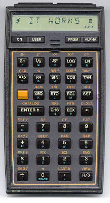
I got it). The ALPHA key sometimes bounces, acting as if I'd pressed
it twice in a row. And there is a strange little pair of bumps on the right
side of the keyboard, next to the SST key (see the close-up photo).
If anyone can tell me what that might be,
I'd appreciate hearing from you.
There are
still a few things that need to be fixed. The cover for the charging jack
is missing (although the calculator didn't come with a rechargeable battery).
One of the port covers is missing (the card reader was plugged into it when
I got it). The ALPHA key sometimes bounces, acting as if I'd pressed
it twice in a row. And there is a strange little pair of bumps on the right
side of the keyboard, next to the SST key (see the close-up photo).
If anyone can tell me what that might be,
I'd appreciate hearing from you.
Well, that's all that I needed to do to get this calculator working again. If you take it a step at a time, it's really not very difficult to do. Just be careful, check all your work as you finish each step, and your chances of success are very high. On the other hand, if you're not comfortable disassembling electronic equipment or working with a soldering iron, you might be better off getting a more experienced friend or colleague to help you out.
If you or somone you know has any HP-41 accessories (especially a module cover, charging jack cover, and keyboard overlays), I might be interested in taking them off your hands if the price is right (i.e. nil to very low). Please contact me.
Finally, if you need any help or advice on repairing your own HP-41, feel free to e-mail me, but please do not be surprised if it takes me a few weeks to get back to you.