WP34S conversion, yet another but with a difference
Message #1 Posted by Geoff Quickfall on 21 June 2012, 5:10 p.m.
Hi all
yet another set of hardware conversion photos but I think these may add to the knowledge set. I will be including these and more for the book and have added two youtube videos (links at end of post) for those of you that have not yet considered the WP34S.
I have used hardware that Katie Wasserman proposed. This includes a trimming cap for the quartz cyrstal assembly which allows the timing accuracy to be adjusted. I have posted this assembly as it is different enough from Alexanders excellent PDF to add to the options.
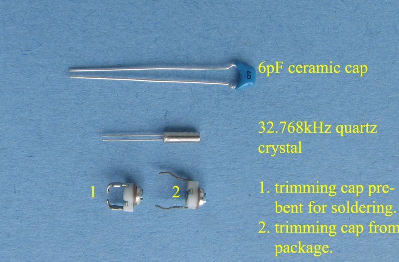
So here are the parts:
timimg hardware:
-crystal..............32.768kHz, 6PF cylinder,
-capacitor............ceramic 6pF 50V radial
-trimming capacitor...2.8 - 20 pFd variable cap
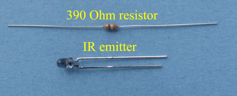
printer hardware:
-emitter..............IR 3MM HI EFF 940NM
-resistor.............390 Ohm 5% axial
Timing hardware:
Printing hardware:
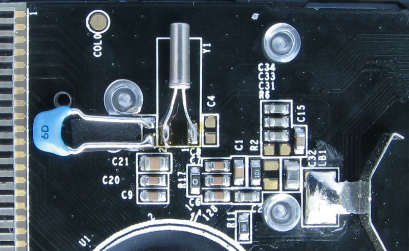
I started by soldering the components to the PCA. I used a handheld, battery operated, fine point soldering iron. All points were pre soldered.
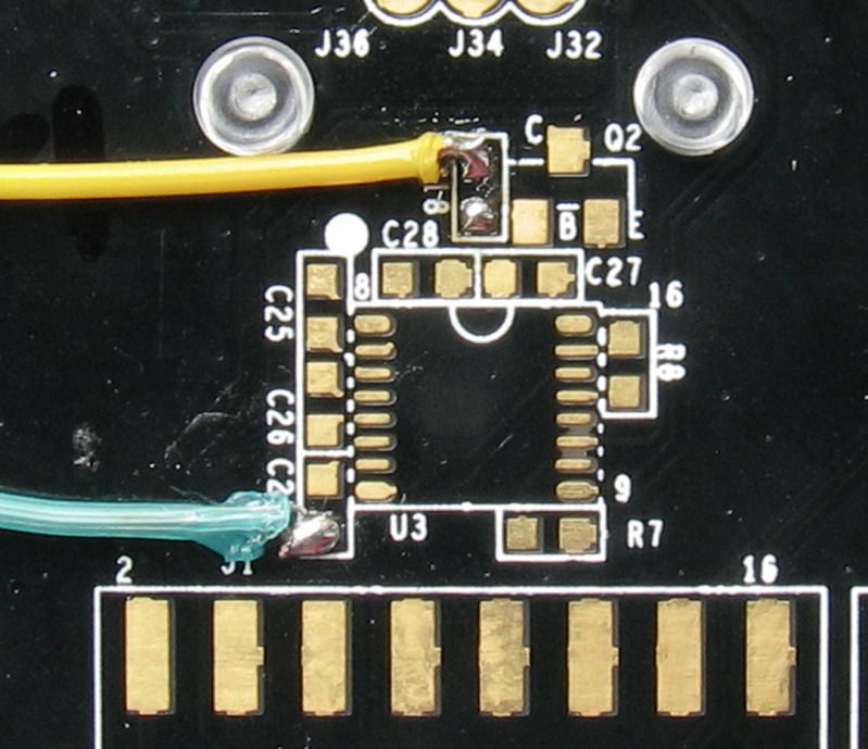
Timing Hardware in place: here we see the quartz crystal and ceramic cap in place. The C4 solder points are used for the trimming capacitor in the next photo.
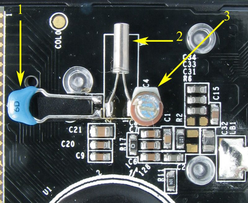
The trimming capacitor is now added. Note that under the blue capacitor's leads, I have placed some electricians tape (small rectangle) to cover to solder points not used and to prevent shorting with the cap legs.
Printer solder points:
In addition to adding hardware to the PCA one must also consider the calculator case. In this example the back shell is a mass of strengthening baffles and ridges which cause problems when hardware is added to the PCA with respect to clearances.
In this photo the yellow boxes represent areas where I removed the ridge. The red box indicates the new hole drilled to allow access to the trimming cap for adjusting the timing accuracy. The trimming cap is also slightly proud of the back shell so the hole not only allows access but also allows the case to close without impacting the cap. You can see the placement I used for the IR emitter and resistor and how it is routed around the LCD and through the milled areas of the bottom shell to the solder points.
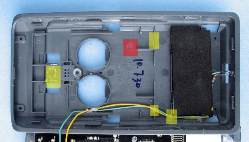
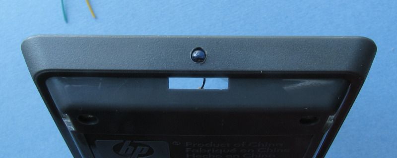
The wires are laid in using the milled areas so that they will not prevent the secure closing of the back shell. I used a 7/64ths bit to drill a hole in the top side of the calc. This allowed a tight friction fit of the emitter for the printer. It also allowed me to position the emitter so it is pointing parallel to the surface of the calculator.
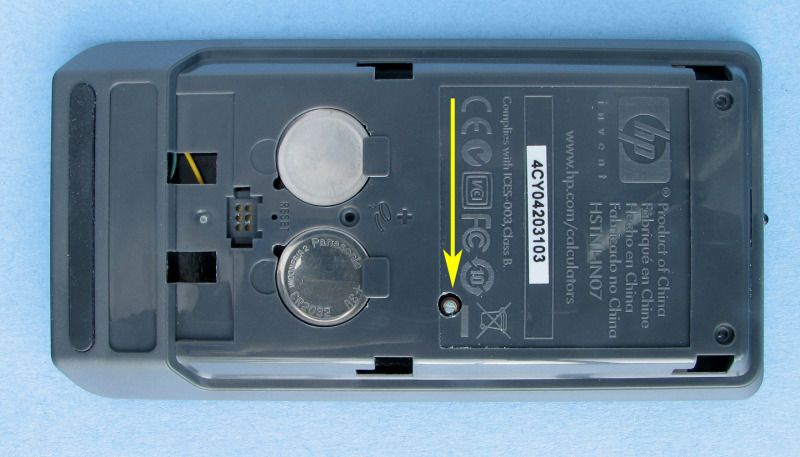
Here is the back shell with the new access hole for the trimming cap. To position the drill, I applied a small drop of paint to the top of the trimming capacitor once it was soldered in place. I then assembled the calc and the paint on the cap was transferred to the inside back of the back shell marking the drilling point:
After placing the back shell (snapped not screwed in place) I checked for fit. Were the wires interfering with a correct fit and etc. Once happy, insert screws and tighten.
Of course I did test prior to the screws being applied. Here are the you tube results:
stopwatch youtube
printer youtube
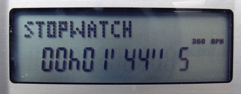
Stop watch:
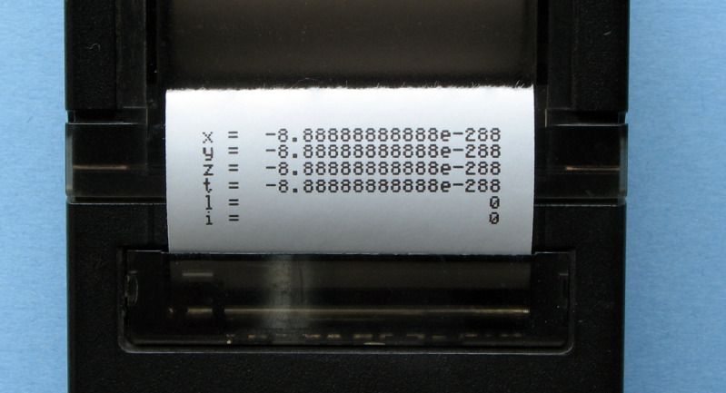
Printer output:
Special thanks to Pauli and Marcus (his mother makes good cookies). Also thanks to Katie for comming up with the added adjusting function for the stopwatch accuracy and Alexander and all the others that have contributed.
Now to program and work on chapter 13 "WP34S conversion".
Cheers, Geoff
edited:
just executed the 'WHO' command so I am adding names to Pauli and Marcus: thanks also Walter and Neil!!!!
32.768 kHz. Or 32,768 Hz. :-)
Edited: 22 June 2012, 11:37 a.m. after one or more responses were posted
| 

