Re: screw hp-15c and 10c
Message #11 Posted by Randy Sloyer on 10 Feb 2004, 7:42 p.m.,
in response to message #10 by George
On the early Voyagers, the logic module was a separate from the keyboard. The two were connected with a flexible circuit and an elastomeric connector on the upper right side of the calculator.
The hole you see under the upper right foot is a pin that projects from the front of the case and fits into the back of the case.
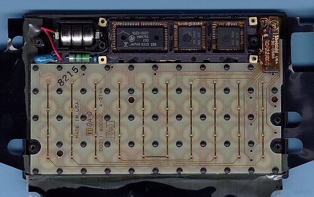
There is a molded "dog bone" in the back of the case that applies pressure on the connector. For this reason, these older, original design Voyagers will not function correctly with the back off the unit as the pressure plate for the keyboard connector is gone. You can see the connector and pins on the upper right side in one of Dave's photos here: http://www.hpmuseum.org/10cint.jpg.
FWIW, the easiest way to tell if your Voyager is a one or two board design is the battery connections. If the connectors are symmetrical, as in the photo above, it is an early version two piece. If there is a spring on the left and gold pin on the right, it is a one piece.
Edited: 10 Feb 2004, 7:43 p.m.
| 