![]() The Museum of HP Calculators
The Museum of HP Calculators
This program was written by Guillermo Castarés and is used here by permission.
This program is supplied without representation or warranty of any kind. The author and The Museum of HP Calculators therefore assume no responsibility and shall have no liability, consequential or otherwise, of any kind arising from the use of this program material or any part thereof.
If you have comments about the program, please write to gcasta@hotmail.com.
The program solves an electric circuit of several nodes or several loops, and works with AC using complex matrix representation of the circuit. It solves DC problems as a subgroup of AC problems.
The circuit has to be specified in an ASCII file, and stored in the extended memory of the calculator. The program reads this file and prepares a complex matrix. This matrix is solved by the PVT program of the Math Module used as subroutine. Finally the program shows a complex vector with the results.
This method of entering data allows the user to modify single parameters or components in a circuit and solve the new circuit without having to enter all the data again! Also it's possible to store different circuits to solve in the extended memory.
The only limit to the number of elements in the circuit is the memory size of the circuit description file. The elements can be specified freely sorted, or with no sort at all.
Another user friendly item of the program is that the user don't need to care about the number of program and data registers (assuming there are a minimum of 15 assigned). The nice "PSIZE" function allows the program to do that.
The program accepts all R or G=1/R, X or B=-1/X, Z or Y=1/Z as well as C and L instead of X.
The program was develop for a HP-41CX with Math module.
It's also possible to use it in a HP-41CV with the X-Functions module and Math module. In this case could be useful have a little editor program to edit the ASCII file in the extended memory, used as input data, because the "ED" editor of HP-41CX will not be there.
I think should be possible too, to copy the "PVT" program from de Math module to use as subroutine when the module is not inserted. Of course this will limit the size of memory available to solve complex circuits.
With the three program routines (EEA, VELS, IELS) loaded in memory, is possible to solve problems up to six Loops/Nodes. With only two program routines (EEA & VELS or EEA & IELS) loaded in memory, is possible to solve problems up to seven Loops/Nodes.
The following table shows the number of data register required, according with the number of Nodes/Loops of the circuit:
Loops/Nodes |
Data Registers |
Elapsed Time to solve* |
1 |
23 |
1' 30" |
2 |
39 |
2' |
3 |
63 |
3' |
4 |
95 |
4' 30" |
5 |
135 |
6' |
6 |
183 |
8' 30" |
7 |
239 |
12' |
(* Approximated. This elapsed time depends on the number of components.)
The program solves circuits by Nodes Voltages and Loops Currents methods. In the first case, only Current Sources are allowed, in the second case only voltage Sources are allowed. If you have to solve a circuit with mixed sources types, then you have to convert all of them to the same type before to solve the circuit.
The circuit is described in an ASCII file in the extended memory. The name of the file can be freely chosen.
The following elements are allowed:
Symbol |
Component type |
V |
Independent Voltage Source |
I |
Independent Current Source |
R |
Resistance |
G |
Conductance |
L |
Inductance |
C |
Capacitance |
X |
Reactance |
B |
Susceptance |
Z |
Impedance |
Y |
Admittance |
The following elements have only one parameter: R, G, L, C, X, B. The following elements have two parameters expressed as a complex number in rectangular form: Z, Y, V, I.
The values of the parameters should be expressed according to the flags 28 and 29 (decimal symbol and digit groups). Here we assumed that flag 28 is "Clear" and flag 29 is "Set".
The first step is to decide if we will solve a Loops Currents problem or a Nodes Voltages problem.
Loops currents
Identify all the independents loops of the circuit and number them beginning from 1 (one). All the currents are supposed clockwise. In consequence, in each branch (component connecting two nodes) the two currents have opposite courses.
If a component belongs to a only independent loop, then it's described as belonging to a fictitious loop identified by 0 (zero) (non independent).
Only voltage sources are allowed. The polarity of them have to be according to the current in the loop
The first register of the input file is:
In
where n is the number of independent loops.
The following registers of the input file describes one component each one:
ncm par1 par2
where:
n is the number of the first loop
m is the number of the second loop
c is the component type
par1 is the value of the component or the real part of it
par2 is the imaginary part of a two parameters component. Assumed 0 if no present.
The last register of the input file is:
END
Nodes Voltages
Node is the join of more than two elements.
Identify all the nodes of the circuit and number them beginning from 0 (zero). The node numbered zero will be the reference one. The nodes numbered from 1 (one) are the independent nodes.
Only Current power supplies are allowed. Conventionally is supposed that them are sending current from the first node to the second node.
The first register of the input file is:
Vn
where n is the number of independent nodes.
The following registers of the input file describes one component each one:
ncm par1 par2
where:
n is the number of the first node
m is the number of the second node
c is the component type
par1 is the value of the component or the real part of it
par2 is the imaginary part of a two parameters component. Assumed 0 if no present.
The last register of the input file is:
END
Starting to solve
Once the file describing the circuit is ready, it is necessary to put the file name in the alpha register to call the "EEA" program:
	Keystrokes:		Display:
 	[ALPHA] FileName
 	[ALPHA]
	[XEQ] [ALPHA] EEA
	[ALPHA]
If there are capacitances or inductances in the circuit then the program will ask for the frequency.
Finally the program will show the real and imaginary parts of each current/voltage on the circuit.
To solve the following circuit we will use the voltage nodes method, because there is a current source.
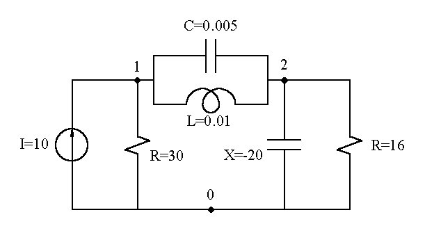
The first step is to identify the nodes and number them from 0. In this circuit there are a reference voltage node (0) and to nodes 1 and 2.
Then we have to create the file with the circuit description:
| Keystrokes: | Display: | Comment: |
|---|---|---|
| [ALPHA] CIRC1 [ALPHA] | 0,0000 | file name |
| 10 [XEQ] [ALPHA] | XEQ _ | file size |
| CRFLAS [ALPHA] | 10,0000 | create file ASCII |
| [XEQ] [ALPHA] | XEQ _ | |
| ED [ALPHA] | 00 T | invoke text editor |
| V2 [R/S] | 01 T | type of circuit and size |
| 0I1 10 [R/S] | 02 T | current source |
| 0R1 30 [R/S] | 03 T | resistance |
| 1C2 0,005 [R/S] | 04 T | capacitance |
| 1L2 0,01 [R/S] | 05 T | inductance |
| 0X2 -20 [R/S] | 06 T | reactance |
| 0R2 16 [R/S] | 07 T | resistance |
| END [R/S] | 08 T | end of file |
| [ON] | 10,0000 | exit editor |
Once the circuit is described and stored in the extended memory, we can solve it:
| Keystrokes: | Display: | Comment: |
|---|---|---|
| [ALPHA] CIRC1 [ALPHA] | 10,0000 | file name |
| [XEQ] [ALPHA] | XEQ _ | invoke the program |
| EEA [ALPHA] | 0I1 10 | shows first component |
| 0R1 30 | shows second component | |
| 1C2 0,005 | ... | |
| FREQ=? | ask for frequency | |
| 50 [R/S] | 1L2 0,01 | shows following component |
| 0X2 -20 | ... | |
| 0R2 16 | ... | |
| END | end of file | |
| V(1)X=83,7467 | V1 real | |
| [R/S] | V(1)Y=-46,7976 | V1 imaginary |
| [R/S] | V(2)X=82,5013 | V2 real |
| [R/S] | V(2)Y=-41,0423 | V2 imaginary |
| [R/S] | V(1)X=83,7467 | shows the first again... |
NONEXISTENT: The file contains a component not supported. The circuit type is "I" and contains a current source. The circuit type is "V" and contains a voltage source.
NO ROOM: There is not enough memory to solve a circuit.
FL NOT FOUND: The specified circuit file doesn't exist.
FL TYPE ERR: The specified circuit file isn't an ASCII file.
Three routines forms the whole program. The first one, "EEA", is always necessary. The second one "VELS" is only necessary to solve Nodes Voltage circuits, and the third "IELS" is only necessary to solve Loop Currents problems.
EEA program:
001 •LBL "EEA"
002  CLRG
003  CLX
004  SEEKPTA
005  GETREC
006  ATOX
007  STO 09
008  ANUM
009  2
010  *
011  STO 14
012  X^2
013  LAST X
014  2
015  *
016  +
017  15
018  +
019  SF 25
020  ARCL IND X
021  FC?C 25
022  PSIZE
023  SF 00
024  SF 01
025 •LBL 08
026  GETREC
027  AVIEW
028  ATOX
029  48
030  -
031  STO 00
032  ATOX
033  STO 07
034  ATOX
035  48
036  -
037  STO 01
038  ANUM
039  STO 02
040  ATOX
041 •LBL 09
042  ATOX
043  44
044  X<=Y?
045  GTO 09
046  CLX
047  ANUM
048  STO 03
049  CLA
050  RCL 09
051  XTOA
052  "}ELS"
053  ASTO X
054  XEQ IND X
055  FC? 00
056  GTO 07
057  FS? 02
058  XEQ 01
059  FC? 02
060  XEQ 03
061  GTO 08
062 •LBL 07
063  CLD
064  SF 02
065  SF 04
066  SF 05
067  CF 06
068  CF 10
069  XROM "PVT"
070  CF 21
071  CLX
072  SEEKPT
073  GETREC
074  ATOX
075  CLA
076  XTOA
077  40
078  XTOA
079  ASTO 09
080  RCL 14
081  X^2
082  LAST X
083  +
084  14
085  +
086  STO 00
087 •LBL 10
088  RCL 14
089  2 E3
090  /
091  1
092  +
093  STO 01
094 •LBL 12
095  RCL 00
096  RCL 01
097  +
098  STO 02
099  CLA
100  ARCL 09
101  RCL 01
102  48
103  +
104  XTOA
105  41
106  XTOA
107  "}X="
108  ARCL IND 02
109  PROMPT
110  CLA
111  ARCL 09
112  RCL 01
113  48
114  +
115  XTOA
116  41
117  XTOA
118  "}Y="
l19  RCL 14
120  2
121  /
122  RCL 02
123  +
124  ARCL IND X
125  PROMPT
126  ISG 01
127  GTO 12
128  GTO 10
129 •LBL "FRQ"
130  FC?C 01
131  RTN
132  "FREQ=?"
133  PROMPT
134  2
135  *
136  PI
137  *
138  STO 08
139  RTN
140 •LBL 01
141  1 E-3
142  STO 05
143 •LBL 05
144  1 E-3
145  STO 06
146 •LBL 06
147  RCL 05
148  RCL 06
149  +
150  INT
151  CF 03
152  1
153  X=Y?
154  SF 03
155  RCL IND 05
156  RCL IND 06
157  XEQ 02
158  ISG 06
159  GTO 06
160  ISG 05
161  GTO 05
162  RTN
163 •LBL 02
164  ENTER^
165  ENTER^
166  R^
167  ENTER^
168  R^
169  *
170  X=0?
171  RTN
172  CLX
173  1
174  -
175  RCL 14
176  *
177  +
178  14
179  +
180  STO 04
181  RCL 14
182  X^2
183  2
184  /
185  +
186  RCL 03
187  FS? 03
188  CHS
189  ST+ IND Y
190  RCL 04
191  RCL 14
192  2
193  /
194  +
195  RCL 03
196  FC? 03
197  CHS
198  ST+ IND Y
199  RCL 04
200  RCL 02
201  FS? 03
202  CHS
203  ST+ IND Y
204  RCL 04
205  RCL 14
206  X^2
207  LAST X
208  +
209  2
210  /
211  +
212  RCL 02
213  FS? 03
214  CHS
215  ST+ IND Y
216  RTN
217 •LBL 03
218  1 E-3
219  STO 05
220 •LBL 00
221  CF 03
222  RCL 05
223  INT
224  X=0?
225  SF 03
226  RCL IND 05
227  XEQ 04
228  ISG 05
229  GTO 00
230  RTN
231 •LBL 04
232  X=0?
233  RTN
234  RCL 14
235  X^2
236  LAST X
237  +
238  +
239  14
240  +
241  STO 04
242  RCL 14
243  2
244  /
245  +
246  RCL 03
247  FS? 03
248  CHS
249  ST+ IND Y
250  RCL 04
251  RCL 02
252  FS? 03
253  CHS
254  ST+ IND Y
255  END
VELS subprogram:
001 •LBL "VELS"
002  GTO IND 07
003 •LBL 82
004  RCL 02
005  1/X
006  STO 02
007 •LBL 71
008  SF 02
009  RTN
010 •LBL 67
011  XEQ "FRQ"
012  RCL 08
013  ST* 02
014  GTO 66
015 •LBL 76
016  XEQ "FRQ"
017  RCL 08
018  ST* 02
019 •LBL 88
020  RCL 02
021  1/X
022  CHS
023  STO 02
024 •LBL 66
025  CLX
026  X<> 02
027  STO 03
028  SF 02
029  RTN
030 •LBL 90
031  RCL 02
032  X^2
033  RCL 03
034  X^2
035  +
036  ST/ 02
037  CHS
038  ST/ 03
039 •LBL 89
040  SF 02
041  RTN
042 •LBL 73
043  CF 02
044  RTN
045 •LBL 78
046  CF 00
047  END
IELS subprogram:
001 •LBL "IELS"
002  GTO IND 07
003 •LBL 71
004  RCL 02
005  1/X
006  STO 02
007 •LBL 82
008  SF 02
009  RTN
010 •LBL 67
011  XEQ "FRQ"
012  RCL 08
013  ST* 02
014 •LBL 66
015  RCL 02
016  1/X
017  CHS
018  STO 02
019 •LBL 88
020  CLX
021  X<> 02
022  STO 03
023  SF 02
024  RTN
025 •LBL 76
026  XEQ "FRQ"
027  RCL 08
028  ST* 02
029  GTO 88
030 •LBL 89
031  RCL 02
032  X^2
033  RCL 03
034  X^2
035  +
036  ST/ 02
037  CHS
038  ST/ 03
039 •LBL 90
040  SF 02
041  RTN
042 •LBL 86
043  CF 02
044  RTN
045 •LBL 78
046  CF 00
047  END
Before PVT call:
R00  First Node/Loop of component
R01  Second Node/Loop of component
R02  First value/Real part of component
R03  Second value/Imagine part of component
R04  Used
R05  Loop variable
R06  Loop variable
R07  ASCII code of component
R08  Frequency (f)
R09  ASCII code of "V" if Node Voltage or "I" if Loop Current
R10  Not Used
R11  Not Used
R12  Not Used
R13  Not Used
R14  Matrix order according with PVT routine: 2*number of independent Nodes/loops
R15 to 4*N^2+4*N+15  Matrix elements according with PVT routine
After PVT call:
R00  Register number of first element of matrix
R01  Loop variable to index Loop/Node number
R02  Register address of real part of result
R03  Not Used
R04  Not Used
R05  Not Used
R06  Not Used
R07  Not Used
R08  Not Used
R09  "V(" or "I(" according with the problem type
R10  Not Used
R11  Not Used
R12  Not Used
R13  Not Used
R14  Matrix order according with PVT routine: 2*number of independent Nodes/loops
R15 to 4*N^2+4*N+15  Matrix elements according with PVT routine
00 End of input file not reached
01 Frequency unknown
02 The component is not a power supply
03 Used to form the equations system
XX All the flags used by PVT routine
![]() Go back to the HP-41 software library
Go back to the HP-41 software library
![]() Go back to the general software library
Go back to the general software library
![]() Go
back to the main exhibit hall
Go
back to the main exhibit hall