![]() The Museum of HP Calculators
The Museum of HP Calculators
The basic problem of the design of a mechanical calculator was how to move a gear an amount proportional to the number to be added. The simple stylus/slide adders had an easy answer to this. The user simply placed the stylus in an appropriate hole and the wheel or slide was moved by the appropriate amount. This was undesirable, however, because there was no way for the user to be sure that the correct number had been entered. Also, in the case of multiplications and divisions, the same number would have to be "dialed in" over and over. These problems lead designers to produce more complicated machines.
The three most common types of calculator mechanisms are described and shown below. (These types do not include the stylus/slide adders since the mechanisms of these are readily apparent to the user.) These sections are followed by examples of other portions of calculator mechanisms.
This design appeared in many business adding machines. The picture above shows one digit in a rocking segment design. The rocking segment is gray and each key has a stop (dark green). After the digit in each row was selected, a crank was usually turned which caused each segment to rotate up as far as it could. (Until it hit the stop on the depressed key.) During this action one (as in this case) to nine cogs engaged the counter wheel (dark blue).
When the crank was returned to its starting position, the segment dropped to its original position. During this operation, the counter wheel was disengaged so the return stroke didn't subtract the digit just added.
One additional complication to such a design was the entry of zeros. On full keyboard designs, users didn't want to bother entering zeros (especially leading zeros) so designers included a mechanism that stopped the segment in each column from rocking unless some number key was pressed. Because of this implied zero, many full keyboard machines didn't include zero keys.
Comptometers worked in the same way except that pressing each digit also caused the segment to rock. Most crank style adding machines also printed. In these there was typically another segment opposite the cogged segment which contained the digits 0-9. Once the segment had been cranked to its maximum position, this placed one of the digits opposite a hammer which then struck the digits. (Typically, there was a single hammer across the entire row.)
An interesting variation was to mount the counter wheels (dark blue) at a right angle to the segments rather than edge-on as shown above. The advantage to this was that by shifting the counters sideways, the segments could drive them from either side. This allowed "adding machines" to do direct subtraction without the need for complementary digits. This design was used in the Bohn Contex calculator.
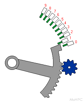
This design dates back to about 1694 and was first used in a machine made by Gottfried Leibniz. Phillip Hann produced an improved machine in 1774 but it was Charles Xavier Thomas who created the first commercially successful version so this type of machine was commonly called a Thomas machine.
The stepped drum solved the problem of having a variable number of cogs by using a drum in which the number of cogs varied along its length. A gear moved along the drum's length would engage a different number of cogs depending on its position.
In the picture above, the Stepped drum was shown in dark gray with the cogs shown in various shades of green. The number gear is above it in light gray and was free to slide along the length of the (dark blue) square shaft. The position of the number gear is determined by where the user set the digit pointer (brown) along a scale (shown in the side view). In this case, the index is set to four, and the number gear just engaged the four longer (darker) cogs on the drum. As the drum continues to rotate, the number gear will miss the five shorter cogs.
The Stepped Drum made a reappearance late in calculating machine evolution as the heart of the Curta calculators. It may seem strange that a mechanism that disappeared due to its large size reappeared in one of the smallest calculating machines ever made. Some early designers created calculating machines that used a single stepped drum surrounded by digit entry devices in a cylinder. Curt Herzstark took this compact design and improved it while shrinking it further to fit in a pocket. In so doing, he created one of the most pleasing calculating machines ever.
The single drum was able to turn each of the counter gears in turn based on their positions along the length of the drum. It led to a design that was simpler, smaller, and less likely to jam than previous designs. The design was first sold in 1948 and sold well until the electronic calculator age.
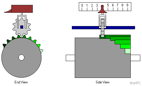
Most stepped drum machines used a set of alternate gears for each counter that were engaged for subtraction. The Curta, however, used a modified drum design that is shown below:
The small teeth shown in light green were thin enough to engage or pass the counter gear depending on the position of the drum along its axis. A small shift of the drum (to the right in the picture) would bring the 10s complement of the number of teeth into contact with each counter gear. The numbers 0, 1 and 9 in the picture show the positions of a single counter gear when the slide was set in the 0, 1 and 9 positions. The blue lines show the path of the counter gear as the drum was turned in the add position and the red lines show the paths when the drum was turned in the subtract position.
In the 1 position, the gear would pass between the first two columns of light green teeth and be turned just once by the last large tooth. In the 9 position, the gear would engage 7 of the small teeth and then the last two large ones.
Shifting to the drum to the subtract position would cause counter gear in the 0 position to engage the entire first column of teeth adding 10 and the 1 position to engage the entire second column of smaller teeth and two large teeth adding 9. The counter in the 9 position would miss the smaller teeth and contact only the last large tooth adding one.
The modified drum also drove the revolution counter wheels with another set of teeth and shifting the drum also caused these counters to be switched to 10s complement mode in the same way. (The sliding switch on the back shifted the revolution counter wheels relative to the drum to undo the effect of drum shifting for certain operations.)
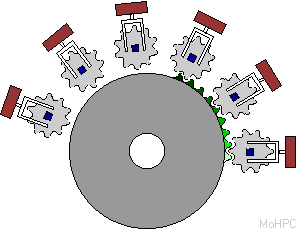
The Stepped Drum machines were used for a long time but they had their problems. The need for the large drums made the machines very large and heavy and they forced both the levers and the display digits to be a long distance apart. In 1872-1877 Frank Baldwin, and later, Willgodt Odhner independently developed calculating machines based on the pinwheel or variable cog wheel. (Brunsviga sold many of these machines using Odhner's patents so they are also commonly called Brunsviga machines.) Baldwin later went on to design the Monroe keyboard calculators.
The Pinwheel consisted of the main wheel body which was fixed relative to the shaft and contained pockets large enough to allow the nine moving pins to drop completely into it. A thin disk with the number setting lever was placed over the main disk. This disk held the pins in place and could be rotated relative to the main disk. This rotation controlled the positions of the pins. The advantage of this design was that the wheels could be made very thin (around a quarter of an inch thick) and could be mounted next to each other allowing for a compact machine with closely spaced levers and numbers. This soon became the dominant form of calculating machine.
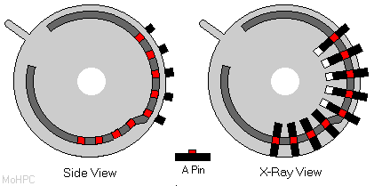
In the picture above, the covering disk is gray and it has a cut-out channel shown in dark gray. The pins are black and have red protrusions that fit into the open channel in the covering disk. The right side shows an x-ray view through the disk and one pin is shown turned on its side between the wheels. By adjusting the lever, the covering disk rotated, the number of pins that stuck out (five in this case) was controlled.
After the lever was set, the crank was turned to turn all the wheels. This caused them to turn the counter wheels by the appropriate amounts. The covering disks moved with the main disks during this operation, so the setting slots on these machines were long enough to allow the levers to rotate inside the machine and back out. Since the number input remained set during operation, these machines, like the drum machines, were well suited to the repetitive operations of multiplication and division.
This design was developed for four function keyboard calculators. It was more compact than the previous designs and well suited to the squarish layout of a keyboard model.
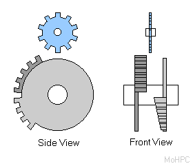
The mechanism used two disks which were pushed apart by a spring. One disk had 5 equal width cogs along part of its circumference. The other disk had 4 cogs of varying lengths.
In the picture, the two disks are in the zero position - neither set of cogs will engage the counter wheel (blue). The disks were squeezed into position by two arms which were squeezed the appropriate amounts by the keys above them. A top view of one set of arms is shown below with a side view of one of the keys to the left.
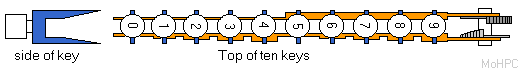
Keys 1-4 caused the right (lower in the picture) disk to be squeezed towards the counter gear to place 1 to 4 cogs in its path. The 5 Key squeezed the left disk towards the center which placed its 5 cogs into the path of the counter wheel. Keys 6-9 squeezed the left disk in as did the 5 key but also squeezed the right disk in by an appropriate amount to place 1-4 additional cogs in the path of the counter wheel.
With the problem of entering variable numbers solved by one of the above methods, the counter gearing was a rather simple affair. The only real challenge was to make them step into place "digitally" rather than moving continuously like clock hands, and keeping them from stepping too far due to their own momentum.
The above picture shows a typical counter in an Odhner style machine. The pinwheel drove the green gear which drove the blue gear which was attached to the black disk with numbers printed along its rim. (On stepped drum machines, the numbers were usually printed on the side of the black disk opposite the gear.) The gray click stop prevented the counter wheel from overshooting during fast cranking which was a major problem with earlier machines. Even with the click stop shown, the gears could sometimes be overthrown when the machines were operated in a jerky fashion, so more elaborate stops were devised. They made it impossible for the counter gear to move without a full back-and-forth pivot of the stop. (Somewhat like a clock escapement.)
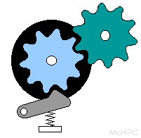
In most calculating machines, all of the digits of both numbers were added at the same time. Regardless of which of the above mechanisms were used, turning the crank caused all them to go into action at once. This was fine except for the problem of carry. Carries had to be handled from right to left after the addition, and the act of adding the carries could necessitate additional carries. The reason the cogs on the pinwheels or drums only went a portion of the way around the circumference was due to the room needed for the carry mechanisms.
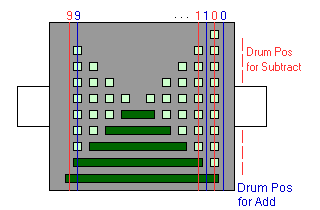
The following picture shows part of the carry mechanism on a typical Odhner-style machine.

(This is the other side of the counter wheel shown above.) On a typical Odhner machine, when a counter digit went from 9 to 0, a wheel (orange) with a single tooth pivoted a hatchet-like projection (gray) out in the path of the next pinwheel to the left. The end of the hatchet had slanted surfaces (light gray) and was thin at the top and bottom but thick in the middle. (See side view inset.) This device had a click stop of its own and stayed in place until it was pushed back.
In addition to the nine digit-pins, each pinwheel had two more pins (one used during subtraction and one during addition.) Rather than moving in and out, these pins were always out but they moved from side to side. In their normal position, they were out of line with the number pins and missed the counter gear. However, the projection from the counter assembly in the next position to the right pushed them in line with the gear so an additional unit was added.
There were two sets of pins because on an Odhner machine, the pinwheels were turned in one direction for addition and the opposite way for subtraction and the carries (or borrows) had to be performed after the addition or subtraction. Also, the carry pins were staggered around the pinwheels so that the rightmost digit was handled first and any carry caused by the previous carry could be added to the left. After the caries were performed, another part of each pinwheel pushed the carry devices back into their normal places.
In addition to the above, mechanisms were needed to zero all the registers. Sometimes a mechanism was included to zero the levers as well. (On ten key adding machines where the number was cleared on each add, a key and mechanism was provided to prevent this while doing multiplications.) Bells were typically provided to indicate underflow and overflow and a great deal of interlocks were typically provided to keep the user from making mistakes including:
![]() Back to early models contents
Back to early models contents
![]() Go back to the main exhibit hall
Go back to the main exhibit hall
![]() To the HP 9100
To the HP 9100