![]() The Museum of HP Calculators
The Museum of HP Calculators
A New Electronic Calculator with Computerlike Capabilities
By Richard E. Monnier
MANY OF THE DAY-TO-DAY COMPUTING PROBLEMS faced by scientists and engineers require complex calculations but involve only a moderate amount of data. Therefore, a machine that is more than a calculator in capability but less than a computer in cost has a great deal to offer. At the same time it must be easy to operate and program so that a minimum amount of effort is required in the solution of typical problems. Reasonable speed is necessary so that the response to individual operations seems nearly instantaneous.
The HP Model 9100A Calculator, was developed to fill this gap between desk calculators and computers. Easy interaction between the machine and user was one of the most important design considerations during its development and was the prime guide in making many design decisions.
One of the first and most basic problems to be resolved concerned the type of output to be used. Most people want a printed record, but printers are generally slow and noisy. Whatever method is used, if only one register is displayed, it is difficult to follow what is happening during a sequence of calculations where numbers are moved from one register to another. It was therefore decided that a cathode-ray-tube displaying the contents of three registers would provide the greatest flexibility and would allow the user to follow problem solutions easily. The ideal situation is to have both a CRT showing more than one register, and a printer which can be attached as an accessory.
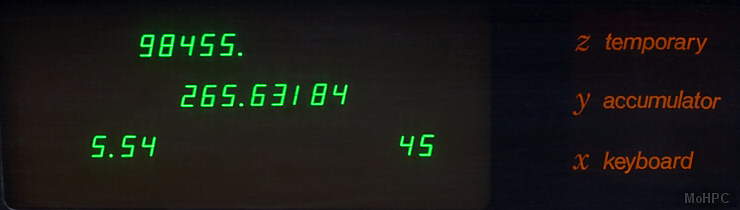
Fig. 2 is a typical display showing three numbers. The X register displays numbers as they are entered from the keyboard one digit at a time and is called the keyboard register. The Y register is called the accumulator since the results of arithmetic operations on two numbers, one in X and one in Y, appear in the Y register. The Z register is a particularly convenient register to use for temporary storage.
One of the most important features of the Model 9100A is the tremendous range of numbers it can handle without special attention by the operator. It is not necessary to worry about where to place the decimal point to obtain the desired accuracy or to avoid register overflow. This flexibility is obtained because all numbers are stored in 'floating point' and all operations performed using 'floating point arithmetic' A floating point number is expressed with the decimal point following the first digit and an exponent representing the number of places the decimal point should be moved--to the right if the exponent is positive, or to the left if the exponent is negative.
4.398 364 291 x 10-3 = .004 398 364 291. The operator may choose to display numbers in FLOATING POINT or in FIXED POINT. The FLOATING POINT mode allows numbers, either positive or negative, from 1 x 10-99 to 9.999 999 999 x 1099 to be displayed just as they are stored in the machine.
The FIXED POINT mode displays numbers in the way they are most commonly written. The DECIMAL DIGITS wheel allows setting the number of digits displayed to the right of the decimal point anywhere from 0 to 9. Fig. 2 shows a display of three numbers with the DECIMAL DIGITS wheel set at 5. The number in the Y register, 5.336845 815 x 10 = 533 684.5815, is too big to be displayed in FIXED POINT without reducing the DECIMAL DIGITS setting to 4 or less. If the number is too big for the DECIMAL DIGITS setting, the register involved reverts automatically to floating point to avoid an apparent overflow. In FIXED POINT display, the number displayed is rounded, but full significance is retained in storage for calculations.
To improve readability, 0's before the displayed number and un-entered 0's following the number are blanked. In FLOATING POINT, digits to the right of the decimal are grouped in threes
A pull-out instruction card, is located at the front of the calculator under the keyboard. The operation of each key is briefly explained and key codes are listed. Some simple examples are provided to assist those using the machine for the first time or to refresh the memory of an infrequent user. Most questions regarding the operation of the Model 9100A are answered on the card.
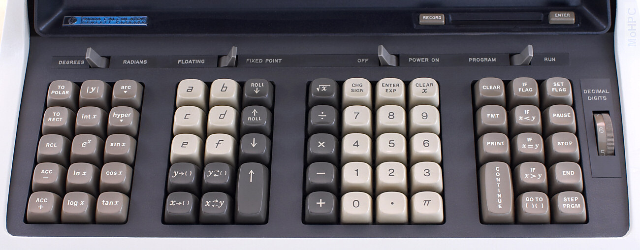
The calculator keyboard is shown in Fig. 4. Numbers can be entered into the X register using the digit keys, the π key or the ENTER EXP key. The ENTER EXP key allows powers of 10 to be entered directly which is useful for very large or very small numbers. 6.02 x 10²³ is entered 6 0 2 ENTER EXP 2 3. If the ENTER EXP key is the first key of a number entry, a 1 is automatically entered into the mantissa. Thus only two keystrokes ENTER EXP 6 suffice to enter 1,000,000. The CHG SIGN key changes the sign of either the mantissa or the exponent depending upon which one is presently being addressed. Numbers are entered in the same way, regardless of whether the machine is in FIXED POINT or FLOATING POINT. Any key, other than a digit key, decimal point, CHG SIGN or ENTER EXP, terminates an entry; it is not necessary to clear before entering a new number. CLEAR X sets the X register to 0 and can be used when a mistake has been made in a number entry.
ADD, SUBTRACT, MULTIPLY, DIVIDE involve two numbers, so the first number must be moved from X to Y before the second is entered into X. After the two numbers have been entered, the appropriate operation can be performed. In the case of a DIVIDE, the dividend is entered into Y and the divisor into X. Then the ÷ key is pressed causing the quotient to appear in Y, leaving the divisor in X.
One way to transfer a number from the X register to the Y register is to use the double sized key, ↑, at the left of the digit keys. This repeats the number in X into Y, leaving X unchanged; the number in Y goes to Z, and the number in Z is lost. Thus, when squaring or cubing a number, it is only necessary to follow ↑ with × or × ×. The roll ↓ key repeats a number in Z to Y leaving Z unchanged, the number in Y goes to X, and the number in X is lost. The roll ↑ key rotates the number in the X and Y registers up and the number in Z down into X. 0 rotates the numbers in Z and Y down and the number in X up into Z. x⇄y interchanges the numbers in X and Y. Using the two ROLL keys and x⇄y, numbers can be placed in any order in the three registers.
The group of keys at the far left of the keyboard, Fig. 4, gives a good indication of the power of the Model 9100A. Most of the common mathematical functions are available directly from the keyboard. Except for |y| the function keys operate on the number in X replacing it with the function of that argument. The numbers in Y and Z are left unchanged. sqrt is located with another group of keys for convenience but operates the same way.
The circular functions operate with angles expressed in RADIANS or DEGREES as set by the switch above the keyboard. The sine, cosine, or tangent of an angle is taken with a single keystroke. There are no restrictions on direction, quadrant or number of revolutions of the angle. The inverse functions are obtained by using the arc key as a prefix. For instance, two key depressions are necessary to obtain the arc sin x: [arc] [sin x] . The angle obtained will be the standard principal value. In radians:
π/2 ≤ Sin-1x ≤ π/2
0 ≤ Cos-1x ≤ π
-π/2 < Tan-1x < π/2
The hyperbolic sine, cosine, or tangent is obtained using the hyper key as a prefix. The inverse hyperbolic functions are obtained with three key depressions. Tanh-1 x is obtained by arc hyper tan x The arc and hyper keys prefix keys below them in their column.
Log x and ln x obtain the log to the base 10 and the log to the base e respectively. The inverse of the natural log is obtained with the ex key. These keys are useful when raising numbers to odd powers as shown in one of the examples on the pull-out card.
Two keys in this group are very useful in programs. int x takes the integer part of the number in the X register which deletes the part of the number to the right of the decimal point. For example int(-3.1416) = -3. |y| forces the number in the Y register positive.
Sixteen registers, in addition to X, Y, and Z, are available for storage. Fourteen of them, 0, 1, 2, 3, 4, 5, 6, 7, 8, 9, a, b, c, d, can be used to store either one constant or 14 program steps per register. The last registers, e and f, are normally used only for constant storage since the program counter will not cycle into them. Special keys located in a block to the left of the digit keys are used to identify the lettered registers.
To store a number from the X register the key x→() is used. The parenthesis indicates that another key depression, representing the storage register, is necessary to complete the transfer. For example, storing a number from the X register into register 8 requires two key depressions: x→() 8 The X register remains unchanged. To store a number from Y register the key y→() is used.
The contents of the alpha registers are recalled to X simply by pressing the keys a, b, c, d, e, and f. Recalling a number from a numbered register requires the use of the y⇄() key to distinguish the recall procedure from digit entry. This key interchanges the number in the Y register with the number in the register indicated by the following keystroke, alpha or numeric, and is also useful in programs since neither number involved in the transfer is lost.
The CLEAR key sets the X, Y, and Z display registers and the f and e registers to zero. The remaining registers are not affected. The f and e registers are set to zero to initialize them for use with the ACC+ and ACC- keys as will be explained. In addition the CLEAR key clears the FLAG and the ARC and HYPER conditions, which often makes it a very useful first step in a program.
Vectors and complex numbers are easily handled using the keys in the column on the far left of the keyboard. Fig. 5 (above) defines the variables involved. Angles can be either in degrees or radians. To convert from rectangular to polar coordinates, with y in Y and x in X, press TO POLAR. Then the display shows θ in Y and R in X. In converting from polar to rectangular coordinates, θ is placed in Y, and R in X, TO RECT is pressed and the display shows y in Y and x in X.
ACC+ and ACC- allow addition or subtraction of vector components in the f and e storage registers. ACC+ adds the contents of the X and Y register to the numbers already stored in f and e respectively; ACC- subtracts them. The RCL key recalls the numbers in the f and e registers to X and Y.
A light to the left of the CRT indicates that an illegal operation has been performed. This can happen either from the keyboard or when running a program. Pressing any key on the keyboard will reset the light. When running a program, execution will continue but the light will remain on as the program is completed. The illegal operations are:
The Model 9100A does all calculations using floating point arithmetic with a twelve digit mantissa and a two digit exponent. The two least significant digits are not displayed and are called guard digits.
The algorithms used to perform the operations and generate the functions were chosen to minimize error and to provide an extended range of the argument. Usually any inaccuracy will be contained within the two guard digits. In certain cases some inaccuracy will appear in the displayed number. One example is where the functions change rapidly for small changes in the argument, as in tan x where x is near 90°. A glaring but insignificant inaccuracy occurs when an answer is known to be a whole number, but the least significant guard digit is one count low: 2.000 000 000 ~= 1.999 999 999.
Accuracy is discussed further in the 'Internal Programming' article in this issue. But a simple summary is: the answer resulting from any operation or function will lie within the range of true values produced by a variation of +/- 1 count in the tenth digit of the argument.
Problems that require many keyboard operations are more easily solved with a program. This is particularly true when the same operations must be performed repeatedly or an iterative technique must be used. A program library supplied with the Model 9100A provides a set of representative programs from many different fields. If a program cannot be found in the library to solve a particular problem, a new program can easily be written since no special experience or prior knowledge of a programming language is necessary.
Any key on the keyboard can be remembered by the calculator as a program step except STEP PRGM. This key is used to 'debug' a program rather than as an operation in a program. Many individual program steps, such as 'sin x' or 'to polar' are comparatively powerful, and avoid the need of sub-routines for these functions and the programming space such sub-routines require. Registers 0, 1, 2, 3, 4, 5, 6, 7, 8, 9, a, b, c, d can store 14 program steps each. Steps within the registers are numbered 0 through d just as the registers themselves are numbered. Programs can start at any of the 196 possible addresses. However 0-0 is usually used for the first step. Address d-d is then the last available, after which the program counter cycles back to 0-0.
Registers f and e are normally used for storage of constants only, one constant in each register. As more constant storage is required, it is recommended that registers d, then c, then b, etc., are used starting from the bottom of the list. Lettered registers are used first, for the frequently recalled constants, because constants stored in them are more easily recalled. A register can be used to store one constant or 14 program steps, but not both.
The bank on the far right of the keyboard, Fig. 4, contains program oriented keys. GOTO ()() is used to set the program counter. The two sets of parentheses indicate that this key should be followed by two more key depressions indicating the address of the program step desired. As a program step, 'GO TO' is an unconditional branch instruction, which causes the program to branch to the address given by the next two program steps. The 'IF' keys in this group are conditional branch instructions. With IF x<y, IF x=y, and IF x>y the numbers contained in the X and Y registers are compared. The indicated condition is tested and, if met, the next two program steps are executed. If the first is alphameric, the second must be also, and the two steps are interpreted as a branching address. When the condition is not met, the next two steps are skipped and the program continues. IF FLAG is also a very useful conditional branching instruction which tests a 'yes' or 'no' condition internally stored in the calculator. This condition is set to 'yes' with the SET FLAG from the keyboard when the calculator is in the display mode or from a program as a program step. The flag is set to a 'no' condition by either asking IF FLAG in a program or by a CLEAR instruction from the keyboard or from a program.
Data can be entered for use in a program when the machine is in the display mode. (The screen is blank while a program is running.) A program can be stopped in several ways. The STOP key will halt the machine at any time. The operation being performed will be completed before returning to the display mode. As a program step, STOP stops the program so that answers can be displayed or new data entered. END must be the last step in a program listing to signal the magnetic card reader; when encountered as a program step it stops the machine and also sets the program counter to 0-0.
As a program step, PAUSE causes a brief display during program execution. Nine cycles of the power line frequency are counted--the duration of the pause will be about 150 ms for a 60 Hz power line or 180 ms for a 50 Hz power line. More pauses can be used in sequence if a longer display is desired. While a program is running the PAUSE key can be held down to stop the machine when it comes to the next PAUSE in the program. PAUSE provides a particularly useful way for the user and the machine to interact. It might, for instance, be used in a program so that the convergence to a desired result can be observed.
Other means of input and output involve peripheral devices such as an X-Y Plotter or a Printer. The PRINT key activates the printer, causing it to print information from the display register. As a program step, PRINT will interrupt the program long enough for the data to be accepted by the printer and then the program will continue. If no printer is attached, PRINT as a program step will act as a STOP. The FMT key, followed by any other keystroke, provides up to 62 unique commands to peripheral equipment. This flexibility allows the Model 9100A to be used as a controller in small systems.
A simple program to calculate N! demonstrates how the Model 9100A is programmed. Fig. 6 (top) shows a flow chart to compute N! and Fig. 6 (bottom) shows the program steps. With this program, 60! takes less than 1/2 second to compute.
After a program is written it can be entered into the Model 9100A from the keyboard. The program counter is set to the address of the first program step by using the GO TO ( ) ( ) key. The RUN-PROGRAM switch is then switched from RUN to PROGRAM and the program steps entered in sequence by pushing the proper keys. As each step is entered the X register displays the address and key code. The keys and their codes are listed at the bottom of the pull-out card. Once a program has been entered, the steps can be checked using the STEP PRGM key in the PROGRAM mode. If an error is made in a step, it can be corrected by using the GOTO ()() key without having to re-enter the rest of the program.
To run a program, the program counter must be set to the address of the first step. If the program starts at 0-0 the keys GOTO ()() 0 0 are depressed, or simply just END since this key automatically sets the program counter to 0-0. CONTINUE will start program execution.
One of the most convenient features of the Model 9100A is the magnetic card reader-recorder, Fig. 8. A program stored in the Model 9100A can be recorded on a magnetic card, Fig. 9 (above), about the size of a credit card. Later when the program is needed again, it can be quickly re-entered using the previously recorded card. Cards are easily duplicated so that programs of common interest can be distributed.
As mentioned earlier, the END statement is a signal to the reader to stop reading recorded information from the card into the calculator. For this reason END should not be used in the middle of a program. Since most programs start at location 0-0 the reader automatically initializes the program counter to 0-0 after a card is read.
The magnetic card reader makes it possible to handle most programs too long to be held in memory at one time. The first entry of steps can calculate intermediate results which are stored in preparation for the next part of the program. Since the reader stops reading at the END statement these stored intermediate results are not disturbed when the next set of program steps is entered. The stored results are then retrieved and the program continued. Linking of programs is made more convenient if each part can execute an END when it finishes to set the program counter to 0-0. It is then only necessary to press CONTINUE after each entry of program steps.
Dick Monnier has a BSEE from the University of California at Berkeley, 1958, and an MSEE from Stanford University, 1961. Dick has been with HP since 1958 when he joined the group working on sampling oscilloscopes. He has been project leader on the Models 120B, 132A and 140A oscilloscopes and the Model 191A television waveform monitor prior to the transfer of the project to HP's Colorado Springs Division. Since early 1966 he has been Section Leader responsible for the 9100A Calculator project in Palo Alto. Dick holds several patents and is a Member of IEEE.
HP Model 9100A
The HP Model 9100A is a programmable, electronic calculator which performs operations commonly encountered in scientific and engineering problems Its log, trig and mathematical functions are each performed with a single key stroke, providing fast convenient solutions to intricate equations Computer-like memory enables the calculator to store instructions and constants tor repetitive or iterative solutions The easily readable cathode ray tuba instantly displays entries answers and intermediate results
DIRECT KEYBOARD OPERATIONS INCLUDE
The program mode allows entry of program instructions via the keyboard into program memory Programming consists of pressing keys in the proper sequence and any key on the keyboard is available as a program step, Program capacity Is 196 steps. No language or code-conversions are required
A self-contained magnetic card reader/recorder records programs from program memory onto wallet-size magnetic cards tor storage. It also reads programs from cards into program memory for repetitive use. Two programs of 196 steps each may be recorded on each reusable card. Cards may be cascaded for longer programs.
Average times for total performance of typical operations including decimal-point placement:
These times include core access of 1.5 microseconds.
![]() Go back to the HP Journal library
Go back to the HP Journal library
![]() Go back to the main exhibit hall
Go back to the main exhibit hall