HP Articles Forum
[Return to the Index ]
[ Previous | Next ]
Control the World with HP-IL/RS-232/41CX + X10
Posted by Egan Ford on 8 Sept 2007, 4:04 p.m.
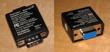
The FireCracker is a small RS-232 powered DB9 dongle. On one end is a DB9 male connector and on the other a DB9 female connector. The FireCracker was designed to be used as a pass-through device. I.e. you can still use your PC or HP-IL/RS-232 serial port for another device. This is accomplished by inserting the FireCracker between the host and the other device.
Because the FireCracker supports pass-through programming is not as straightforward as programming other serial output devices (e.g. printers). Each FireCracker/X10 command is a string of 40 bits, but instead of sending 5 bytes down the traditional data transmit line of the RS-232C interface, we toggle the Data Terminal Ready (DTR) and Request To Send (RTS) lines to send 0's and 1's. Fortunately the HP-IL/RS-232 interface supports this level of control.
The FireCracker derives its power supply from either the RTS or DTR signals from the serial port. At least one of these signals must be high at all times to ensure that power is not lost from the FireCracker.[2]
Signal          RTS     DTR
Reset           0       0
Logical '1'     1       0
Logical '0'     0       1
Standby         1       1
To send a 0 or 1 lower then raise the appropriate line, never lower both. E.g. to send 101, first lower RTS and DTR to reset the FireCracker, then raise DTR and RTS to standby mode. To send the first 1 lower DTR, then raise DTR. To send the 0, lower RTS, and then raise RTS. To send the last 1 lower DTR, then raise DTR.
Every FireCracker/X10 command is 40 bits long. The specification can be obtained from [2]. IANS, the first 16 bits is a static header, the next 16 is our data, and the last 8 is a static footer. The data bits are created by two values, the address of the device to control and the action to perform.
Addresses are labeled A1-A16 - P1-16 for a total of 256 devices that can be controlled. Actions are limited to on, off, bright, dim. There is no way to query the current state of the target device. But you can always change the state to exactly what you want. E.g. power on, send 5 dim commands, etc... If you power off, then back on, the dim is forgotten. There is no way other than visual inspection (or some other type of sensor) to determine if an action actually took place. I.e. there is no feedback or error notification. Think about something else for mission critical applications (e.g. your home made automatic pet feeder).
Generating the 16 data bits is nontrivial; evidence of this is in the length of the specification. 85% of the specification is the data bit patterns. There is no logical correlation between bit position, addresses, or actions. There is some order, but there could be more. A table will need to be created of 32 values once and saved for future use. See [2] for more detail.
Compared to the 71B/GPS article [3] this is a breeze. There are only 4 commands that we need to use:
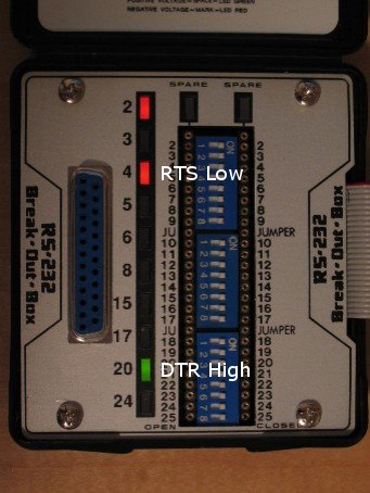
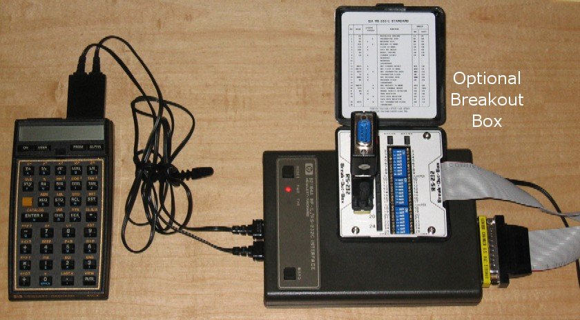
LI1	DTR High
LI2	DTR Low
LI3	RTS High
LI4	RTS Low
E.g. connecting a breakout box in-between the FireCracker and the HP-IL/RS232 interface and sending LI1;LI4 (the ; is a command separator required by the HP-IL/RS232 interface) yields:
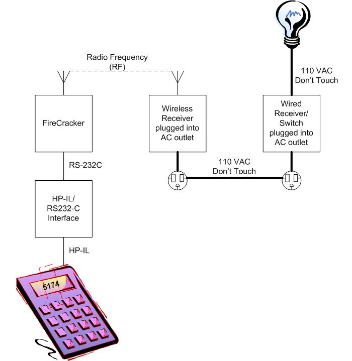
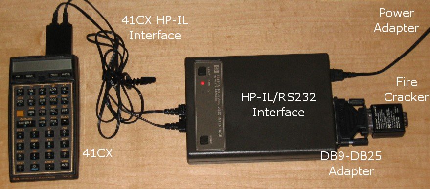
Use the following diagrams to assemble your 41CX home automation system. NOTE: 41CX Extended I/O Module not required.
Optional breakout box setup:
;X10 ;Protocol: http://software.x10.com/pub/manuals/cm17a_protocol.txt ; ;Place device address in ALPHA register, e.g. E2 ;Place a value -19 to 20 in the X register ;X = -19 to -1 = number of times to click dim ;X = 1 to 19 = number of times to click bright ;X = 0 = off ;X = 20 = on ; LBL "X10" ASTO 32 ;STO X10 address (A1-A16 - P1-P16) STO 33 ;STO action (0=OFF, 20=ON, 1-19=BRIGHT, -(1-19)=DIM) SF 25 ;ignore next error "X10.DAT" ;file containing address bits FLSIZE ;size of file? to check if file exists FC?C 25 ;if error (file not found) create file, clear ignore next error flag XEQ 30 ;create X10.DAT with address bits "X10.DAT" ;file containing address bits 0 ;set pointer to register 0 SEEKPTA 000.031 ;load up registers 0-31 from X10.DAT GETRX AUTOIO ;initialize firecracker "HP82164A" FINDIO ;FINDID (XROM 28,28), hp41uc defines it as FINDIO? SELECT REMOTE "LI2\x3bLI4" ;set DTR/RTS low, reset mode, using \x3b for ; because of hp41uc use of ; for comments OUTA "LI1\x3bLI3" ;set DTR/RTS high, stanby mode, using \x3b for ; because of hp41uc use of ; for comments OUTA CLA ;clear alpha register ARCL 32 ;restore x10 address ATOX ;get ASCII code 65 ;subtract 65 to get A-P as 0-15 - RCL IND X ;rcl x10 A-P address bits 4096 ;left shift 12 bits * STO 34 ;sto in 3420 RCL 33 ;off? X=0? GTO 10 X=Y? ;on? GTO 11 X<0? ;dim? GTO 12 GTO 13
LBL 10 ;off bits 32 STO+ 34
LBL 11 ;on bits + 2nd part of address from ALPHA register ANUM 15 + RCL IND X STO+ 34 0 STO 35 ;sto count GTO 20
LBL 12 ;dim- bits CHS 16 STO+ 34 RDN
LBL 13 ;dim+ bits 136 STO+ 34 RDN STO 35 ;sto count GTO 20
LBL 20 ;build 40 bits 213 STO 45 ;header byte 1 170 STO 44 ;header byte 2 173 STO 41 ;footer byte RCL 34 256 / INT STO 43 ;data byte 1 RCL 34 256 MOD STO 42 ;data byte 2
LBL 35 ;count loop for dim/bright 5 STO 40 LBL 21 ;loop for 5 bytes/40 bits RCL 40 40 + RCL IND X X<>F 8 STO 39 LBL 22 ;loop for 8 bits RCL 39 1 - STO 38 FS? IND 38 XEQ 23 FC? IND 38 XEQ 24 DSE 39 GTO 22 DSE 40 GTO 21 DSE 35 GTO 35
LOCAL ;No REMOTE 0 ;clear flags X<>F CLA ;clear ALPHA ARCL 32 ;restore X10 address RCL 33 ;restore X register arg RTN ;END
LBL 23 ;send 1 bit "LI2" ;set DTR low OUTA "LI1" ;set DTR high OUTA RTN
LBL 24 ;send 0 bit "LI4" ;set RTS low OUTA "LI3" ;set RTS high OUTA RTN
LBL 30 ;load up X10.DAT 34 CRFLD 6 STO 00 7 STO 01 4 STO 02 5 STO 03 8 STO 04 9 STO 05 10 STO 06 11 STO 07 14 STO 08 15 STO 09 12 STO 10 13 STO 11 0 STO 12 1 STO 13 2 STO 14 3 STO 15 0 STO 16 16 STO 17 8 STO 18 24 STO 19 64 STO 20 80 STO 21 72 STO 22 88 STO 23 1024 STO 24 1040 STO 25 1032 STO 26 1048 STO 27 1088 STO 28 1104 STO 29 1096 STO 30 1112 STO 31 0 SEEKPTA 000.031 SAVERX RTN END
Enter the address of the device in the ALPHA register as A1-A16 - P1-A16, e.g. E2. Then enter into the X register a number between -19 and 20, where 20 is on, 0 is off and any other number is the number of times you want to brighten or dim. The documentation indicates that each bright and dim request changes the light by 5%, in practice that is not true. I'd say it's closer to 10%.
After entering the values for device address and action, XEQ X10 then wait ~40 seconds. Each bit takes about 1 second to send. If you are trying to impress someone XEQ X10 first, then start to explain how it works. NOTE: The registered EMU41 with HP-IL adapter in fast mode takes a few seconds.
After execution the ALPHA and X registers will be restored to their initial state so that a follow up action can be entered quickly.
So far all that I have described is an expensive remote for the FireCracker/X10 home automation system. BTW, you get a remote as part of the system. But, can the free remote wake up and turn on and off the lights? No! But your 41CX can!
LBL "LGTON" "E2" ;address of device 20 ;20 = power on X10 ;X10 program RTN ;endLBL "LGTOFF" "E2" ;address of device 0 ;0 = power off X10 ;X10 program RTN ;end
"^^LGTON" ALPHA SHIFT ENTER SHIFT ENTER LGTON ALPHA 0 0 18.00 Turn on lights at 6 PM. XYZALM XEQ ALPHA XYZALM ALPHA"^^LGTOFF" ALPHA SHIFT ENTER SHIFT ENTER LGTOFF ALPHA 0 0 23.00 Turn off lights at 11 PM. XYZALM XEQ ALPHA XYZALM ALPHA
Using the timer functions of the 41CX you can easily set the mood without being too obvious.
My development environment consists of a 200 Mhz Pentium Overdrive-based Red Hat 9 Linux workstation with 32MB of RAM and an HP 82973A HP-IL ISA card. I use the registered version of EMU41[4]+DOSEMU to emulate an HP-IL equipped 41CX. Exploiting Linux allows me remote access from my notebook to develop and test 41CX/HP-IL applications quickly and easily. After development is complete it takes only a few seconds via HP-IL to transfer the application to a physical 41CX for final verification. This workstation can also extend the functionality of a physical 41CX by emulating an HP-IL display, printer, and floppy.
Unlike the 71B where BASIC editing is very quick and easy, 41CX/EMU41 RPN entry and editing can be laborious. Fortunately there are options. I use a standard text editor to write all my 41CX code including comments. The code can then be "compiled" by the wonderful HP41UC[5] utility, then loaded in to EMU41 for testing. E.g.:
;my cool program
LBL "COOL"		;always comment your code
"41CX IS SOO COOL"	;put string in alpha register
AVIEW			;show the string
END			;end of program
del cool.lif
hp41uc /t=cool.rpn /l=HDRIVE2.DAT
[DEVICES]
DISPLAY
HDRIVE1
HDRIVE2 HDRIVE2.DAT
LPRTER1
DOSLINK
XIL 1700
"HDRIVE2"	F4 HDRIVE2 F4
FINDID		F8 F4 FINDID F4
The number 3 should be returned to the stack if HDRIVE2 is the 3rd device listed in EMU41.INI
SELECT		F8 F4 SELECT F4
"COOL"		F4 COOL F4
READP		F8 F4 READP F4
1
SELECT		F8 F4 SELECT F4
Using the 41CX for home automation would have been a hit in the 80s. Today it is of no practical use other than a learning aid and some mild entertainment.
Edited: 25 June 2008, 12:27 p.m.