 |
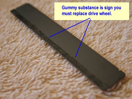
If you have signs of gummy substances on your cards,
after running them through the reader, the drive wheel may need to be replaced.
Other signs are irratic card movement, no movement, slow movement or
errors. |
 |
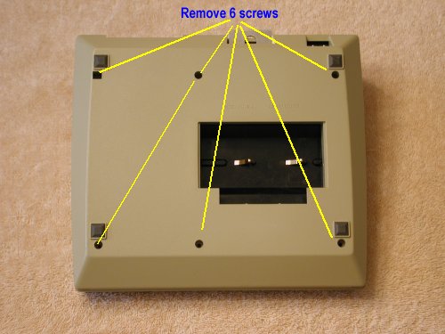
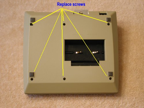
The first thing you must do is to remove the case
back. This is not difficult but there are some precautions you must be aware
of. Just remove the 6 screws shown and the case back can be removed. You
may want to remove the battery and battery cover first. |
 |
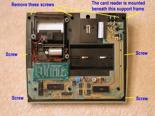
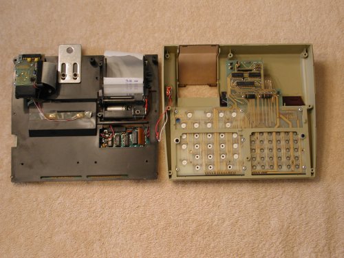
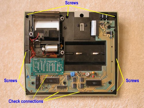
To remove the interior support frame, remove the
screws shown. The card reader is mounted under this frame, in the upper right.
|
 |
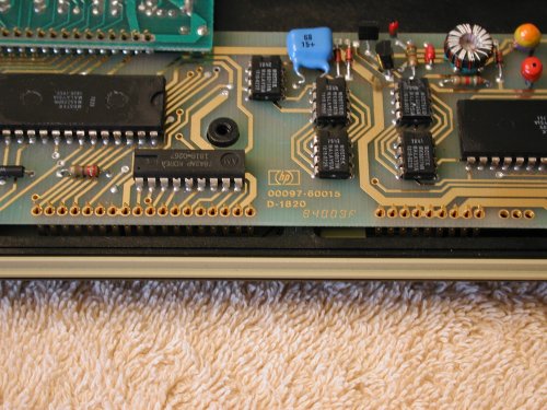
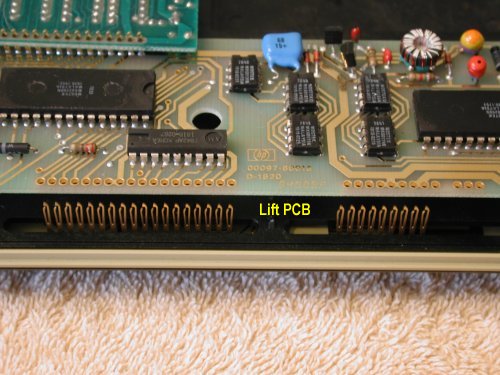
After these 7 screws are removed, you can flip the
main frame over to the left but first you should understand how the main
PCB connects to the keyboard. Failure to understand this can lead to bent
pins when reassembling. |
 |
Simply lift the main PCB and it will come free of
the keyboard/display connector. When you reassemble this, be careful to observe
proper mating, or you may wind up with bent pins. |
 |
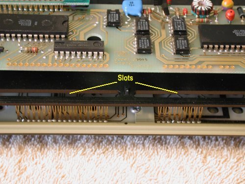
You will notice that there is a slot in the frame.
This slot is to allow the keyboard/display contacts to pass through the frame.
When assembling, be careful to see that these contacts pass through this
slot. If you don't... you get it... more bent pins. |
 |
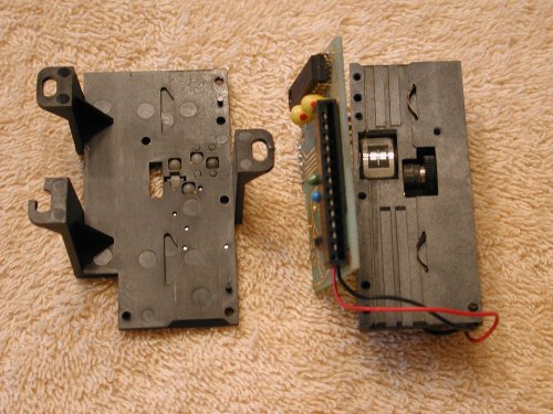
Now that the frame if free of the case and keyboard,
simply flip it out to the left. Be careful not to put too much tension on
the printer switch connections. These can break off easily. You may want
to make note of the colors and positions of wires. Leave a short strip of
paper in the reader. I have found this makes testing easier. |
 |
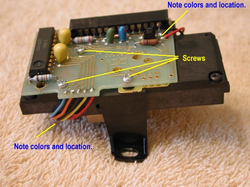
The card reader is mounted to the frame by 3 silver
colored screws. There is also a ribbon cable that connects to the PCB as
shown in the photo. Two of the screws are beneath the ribbon cable. |
 |
Carefully pull the ribbon straight out to the right,
to disconnect it from the reader. Use your hand and NOT
a screwdriver that is shown in the photo. That is simply there to hold the
ribbon back for the photo. Then remove the three silver colored screws. This
will free the card reader from the frame. |
 |
You may want to make note of the colors of all wires
and their connection points. These wires tend to break off when opening up
the reader. Remove the 3 silver colored screws shown in the photo. |
 |
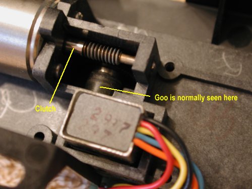
Flip the card reader over and take a look at the
drive wheel. You may see goo on the wheel. You may want to perform this step
before removing screws but it can be done in any order. This photo does not
show the goo that is typical but will be replaced anyway because of age.
|
 |
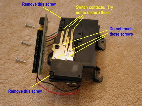
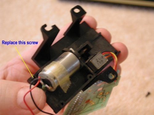
After you remove the 3 silver colored screws, you
can move the PCB to the side of the reader. A couple of cautions here. Remove
the tape to free the red and black wires, if they are taped to motor. Also,
be careful to avoid damaging the switch contacts. Then, remove the two screws
shown, in the photo. |
 |
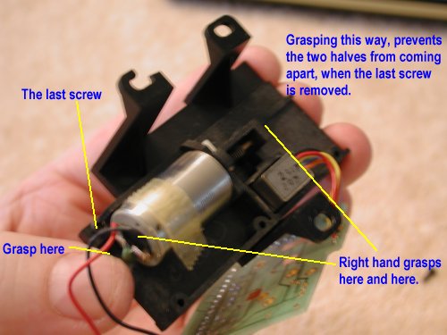
This part is tricky. Flip the card reader over and
grasp in the left hand as shown. Then remove the last screw at the back of
the motor. With the right hand, grasp the motor half of the reader and pull
it off of the switch half. You must observe this orientation
(feet up), or you will lose then nylon balls. |
 |
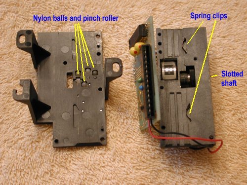
If you have done this correctly, you should see 4
nylon balls and one pinch roller on the left half and two copper spring clips
on the right half. Remove these for safekeeping, until they need to be installed.
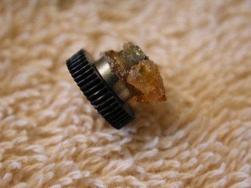
You should clean these parts before reinstalling. Remove the slotted shaft,
indicated in the photo, to remove the gummy drive wheel. |
 |
Gummy wheels typically look like this. Clean all
the gum off of the drive wheel. Be sure to check and clean the interior of
the wheel where the shaft is inserted. This can sometimes have goo and will
slow the motor. |
 |
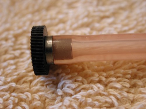
I use pink silicone tubing that I get from a local
model shop. The outside diameter is almost perfect and the inside diameter
is tight enough that I don't have to use any glue. Push the tubing over the
shaft and make sure it is fits evenly all the way around. |
 |
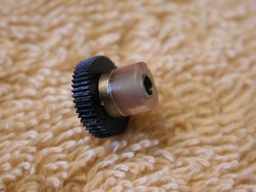
Trim excess tubing flush to the metal. Make sure
the tubing does not extend beyond the metal end. If it does, it may drag
on the frame. I trim it a little smaller to avoid rubbing. |
 |
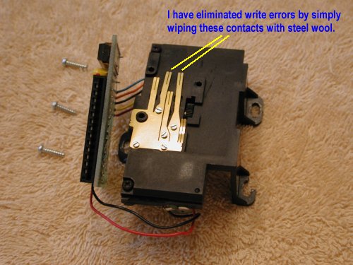
Clean the card reader surfaces and the read/write
head before putting the reader back together. Install the nylon balls, pinch
roller and spring clips. Make sure they are clean before installing. |
 |
Reverse the process that you used to disassemble.
The left hand grasps the half that has the nylon balls (feet up) and the
right hand places the other half on top. Replace the screw shown in the photo.
Tip: Practice this without the loose parts first.
Finally, install the reader PCB and replace the 3 silver color screws.
|
 |
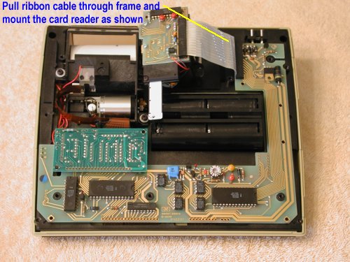
To test the card reader, assemble the frame and case
as shown. Don't forget to connect the keyboard and display connector. Then,
pull the ribbon cable through the frame and attach the card reader. This
makes it easy to test without assembly and disassembly. Adjust slotted shaft
until the card reads and writes properly. |
 |
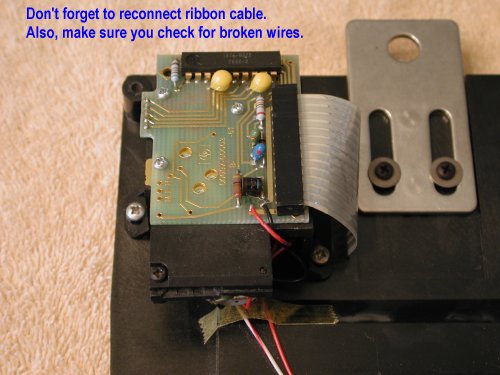
When you have the card reader working properly, remove
the ribbon cable. Thread it back through the slot and reinstall the card
reader. Reconnect the ribbon cable. Check for broken wires before closing
case. Note: There are slots in the reader feet. Adjust position of reader
so that cards to not touch case, as card exits case slot. This takes
practice. |
 |
Install the 7 screws that hold the frame in place.
Check that the keyboard/display connection is mated properly. Check that
you have not disconnected the printer. NOTE: Be careful with the top center
screw. The screw post is fragile and breaks easy. Just make it snug. |
 |
Replace the final 6 screws in the case and your done.
That wasn't hard, was it? |

