HP Articles Forum
[Return to the Index ]
[ Previous | Next ]
HP-42S with Electroluminescent screen and simple I/O port
Posted by Jose Poyan on 26 Mar 2013, 4:45 p.m.
This project is about modifying an HP-42S to include an electroluminescent back lighted display which would look very similar to an LED display but in blue-green colour. The aim was to make a prototype that looks a exactly the same as a normal HP-42S externally except for the display colour when off (black) and I even wanted to do a custom box and show it as a finished new model, let’s call it HP-42EL or HP-42EX (electroluminescent-expandable). The calculator would have included a very primitive I/O port using the keyboard. That was when I had access to a full equipped workshop. But that has changed and I am pretty much sure that I will not have access to it for many years to come. Hence I wanted to share my ideas with the users in this forum, but it is a bit of a shame for me that I can not make the article I wanted originally. The prototype was never completed, but very fortunately I took a couple of (cell phone) pictures of the prototype display fired up (tested on an old HP17B), and I did the dimensions to pack a Li-Ion battery into the case for a very short running time, which is a proof that it would have worked. This article is based in those pictures. Hopefully someone can used them to make his own electroluminescent calculator if he feels motivated...and has a workshop :-)
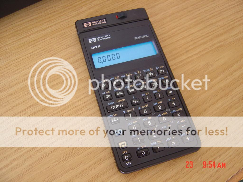
When I was young I wanted to replace my aged and only calculator, a VFD vacuum fluorescent display Casio FX-110 with that horrible keyboard. I fixed in my mind that I wanted the same display but a more powerful machine, and RPN. But I could not find it nowhere. At that time I simply could not understand why no company would attempt to combine the excellent VFD display with a good set of functions. I finally bought an HP32SII but I always wanted THAT imaginary calculator or one with LED display since I had access to an HP25C...so I though I could make one. I know a lot about electronics, in a scale of 1 to 10, I give myself a...0. Since I am an total ignorant in electronics I concentrated in another thing... the mechanical aspect of the construction. And I found there were opportunities with Pioneer model. I first took the HP-20S.
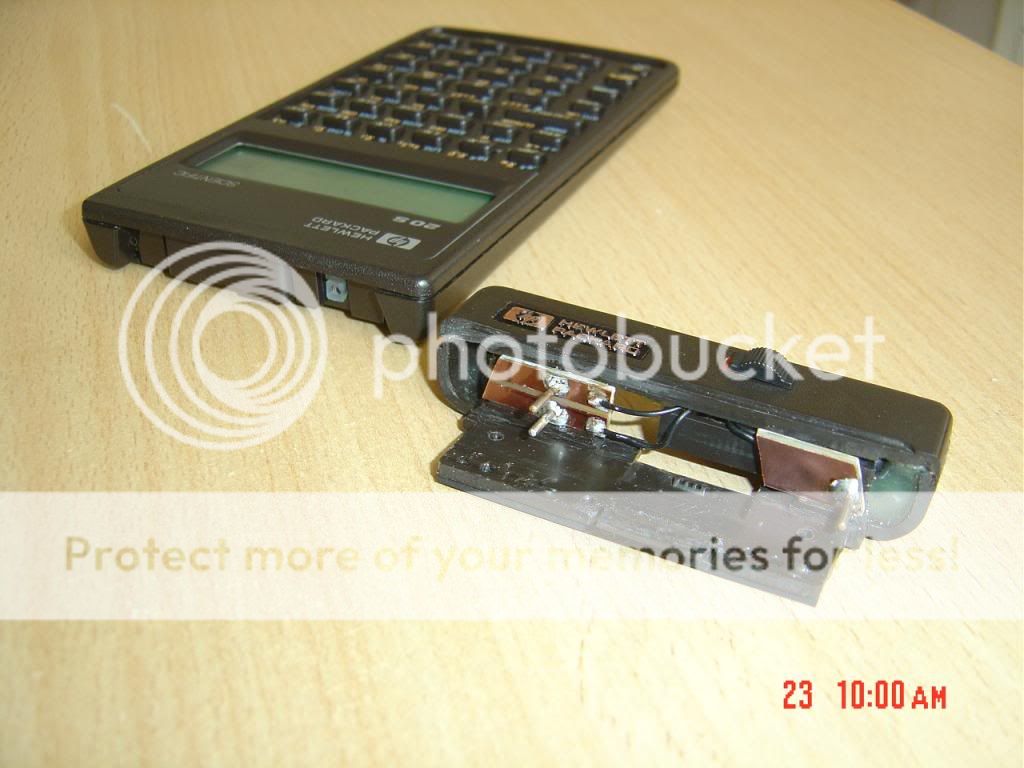
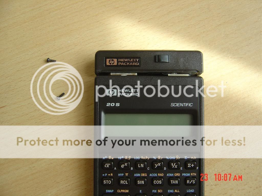
The original LCD display had its back film removed. A paper thin electroluminescent film was put instead. There was just about the right space to slide it from one side, in between the display glass and the mother board. (text describes the forward picture) The top was cut off from an almost destroyed HP17B. The top is removable and the calculator will run on its own batteries like a normal HP20S.
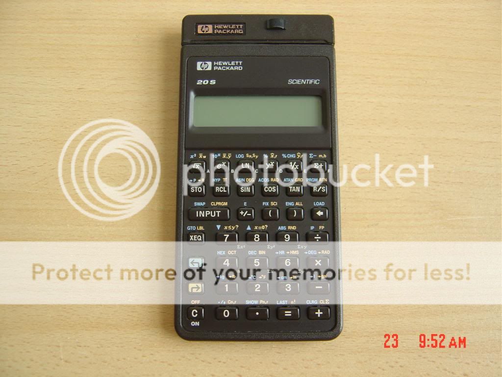
It does not look the same. The screen is a bit darker because the silver back film is not there anymore to reflect the light.
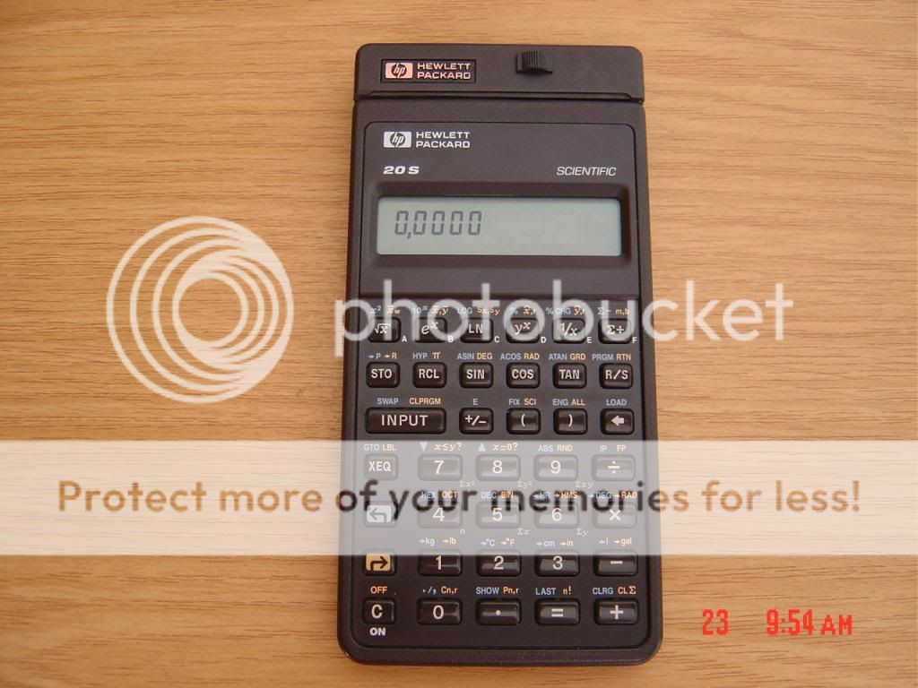
Turned On to make reading easier. It is more blue light than turquoise.
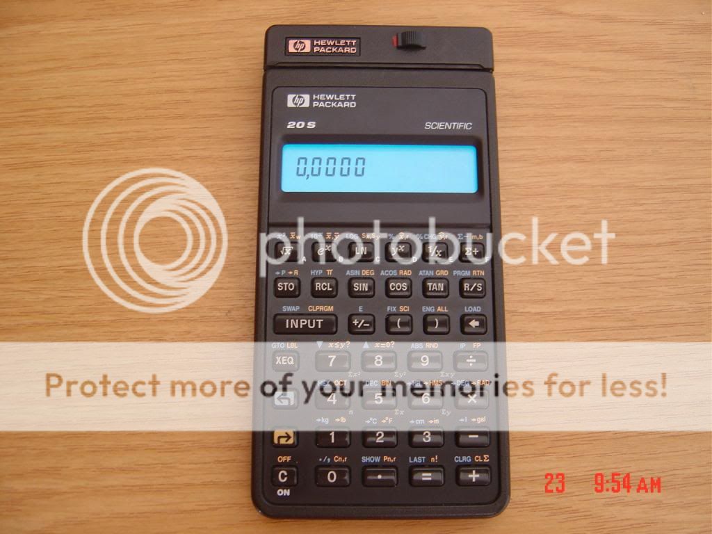
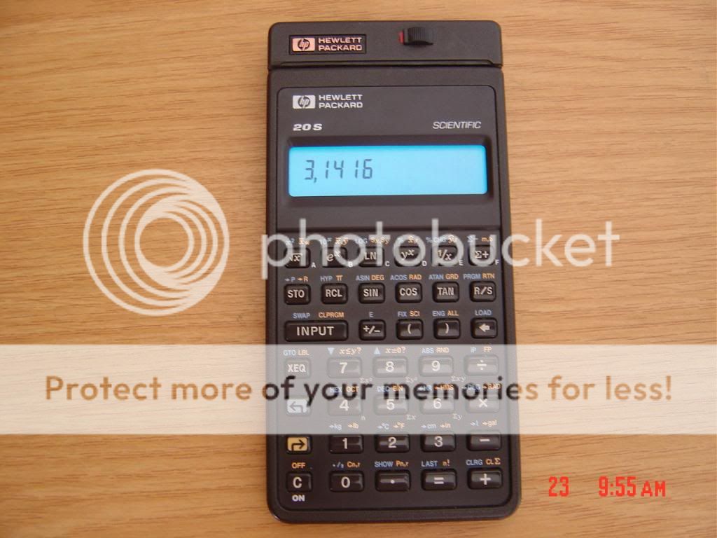
This is a more realistic view. The backlight is not so bright:
A power generator for one single 1.5Volt cell was used, bought online with the electroluminescent film. The circuit was packed and glued inside the box.
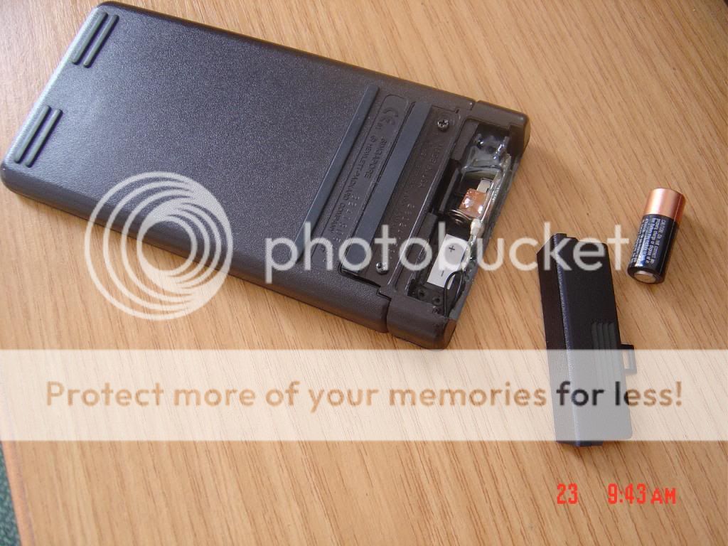
The battery fits just fine.
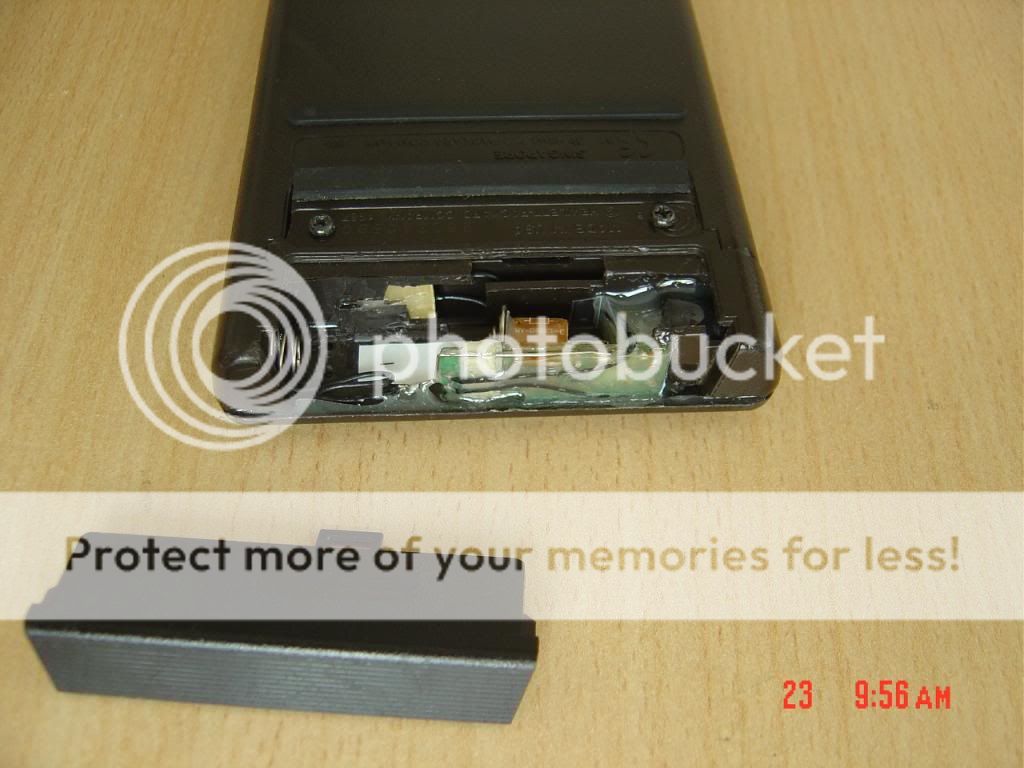
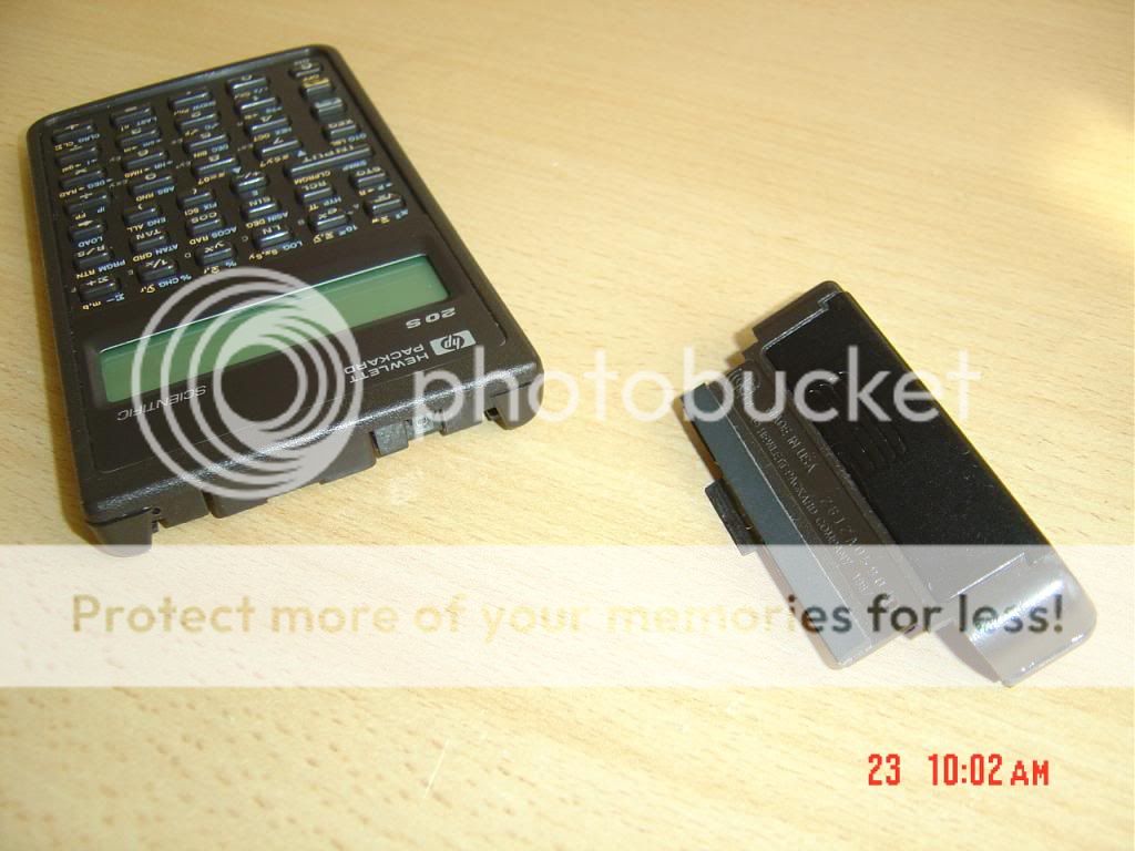
The power unit is fully removable. The battery cover can be put back on the calculator. The couple of contacts are for power. The single contact is there to keep it firm.
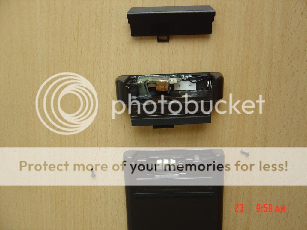
It was not firm enough so two screws needed to be installed.
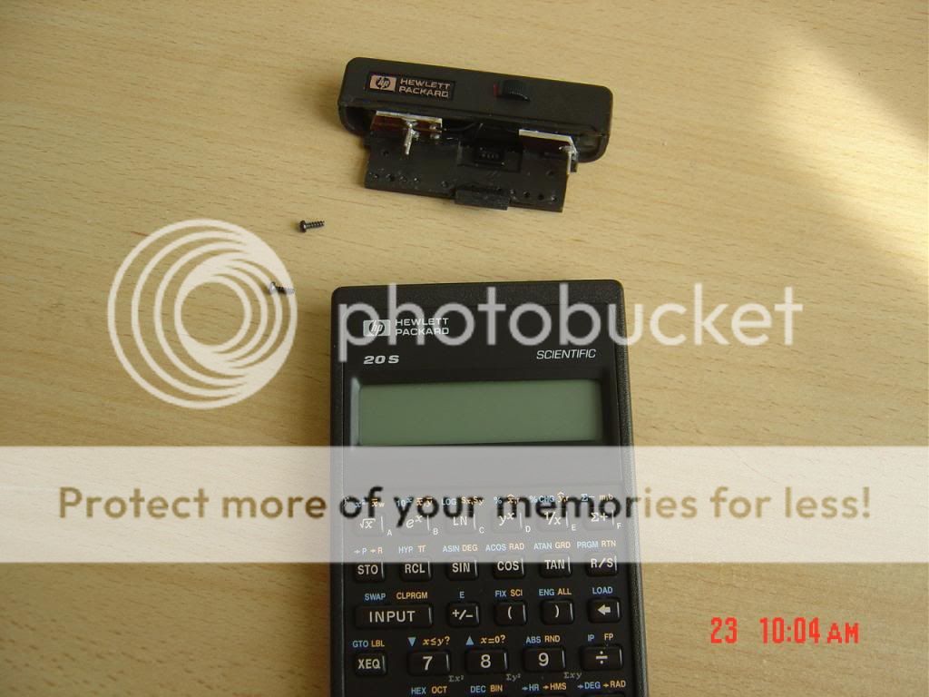
Slightly out, showing the contacts.
The power unit does not generate enough power to give a pleasant glow in the display. The top removable box feels fragile and it would not be a good idea to carry the calculator in a pocket. It took a lot of work but at least this project was finished.
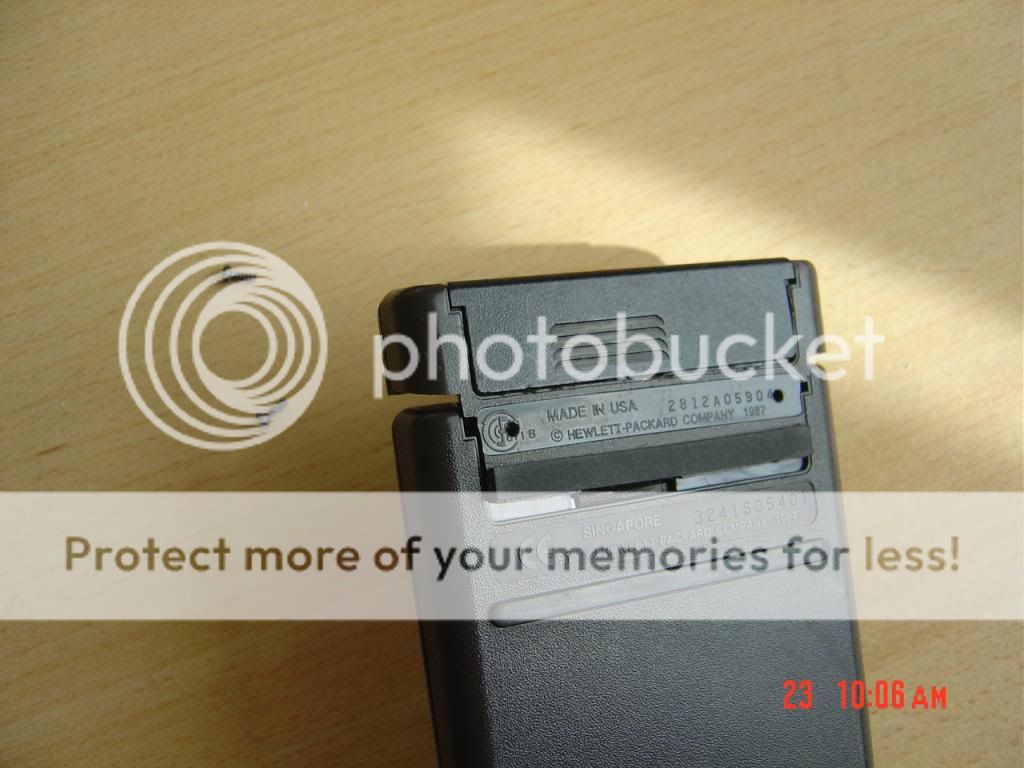
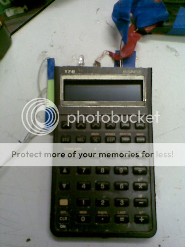
This is the HP17B used for the project. This machine, bought online, was the most abused calculator ever seen by this user. Someone had hit it badly in its corners against the floor and it had pray open marks all around the case made with a big screw driver. At some point the tool found its way in between the shells and scratched deeply the front of the display, but miraculously it did not brake it. It was this what motivated the writer to experiment with this unit. Nevertheless the keyboard and screen were still working fine in this US model ! I love HP vintage calculators.
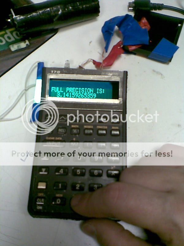
The top was cut to make the HP20S. The original back film of the LCD was removed. A new polarized film was placed but without the silver back. A lot of tests were done to find the best angle of polarization so the light pass through the digits with maximum bright when the user is sitting normally in front (case: myself). The idea was to emulate the LED display so the polarization was inverted. The electroluminescent film is powered here by a electroluminescent power source with 6AA batteries with give more than 100V AC on the left cables. The upper cables feed the calculator. The calculator shells just snap together allowing for testing the life display every time.
This is the picture this article is all about ! Several electro colours were tested. Originally red. But red turned out to be pink and not real LED pure red ! The same happened with turquoise which was the preferred colour for the writher emulating the Casio VFD. But it was actually light blue. Finally this green was found to be the best colour. Its really pleasant to see. It is slightly overdriven as it will be explained which makes it to shine really well.
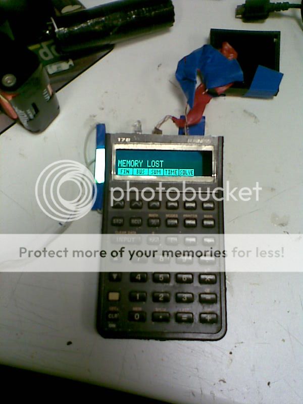
A second picture. The power supply was for testing. The prototype would have had a very small power source for two cells. Now that gives 3V. An this would be run with a Li-Ion Nokia 3.7 V BL-4C mobile battery. Over running the display would give the same bright on tests as this picture shows here ! (I never liked green a lot, but I loved this green, it is hypnotic, nice, like a red LED)
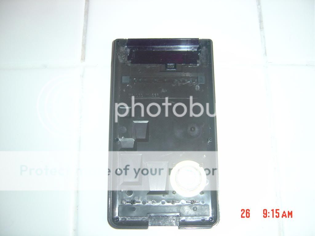
The first idea to power the display was to use micro Li-Pol cells that would cover all and every free space in between the lower shell and the mother boar and would look as the carpet bombs on the skin of a Russian tank. Many sketches were done, concluding that it was possible to put up to 10 of them. But for the sake of simplicity the plan changed to one single Nokia cell. This had exactly the dimensions to be placed just on above the chip. But it would be needed to remover the central hook for the LCD and to cut the lower shell. It was necessary to make a tilted table to cut it, see later.
This picture shows the upper part emptied to allocate the power generator. Although there are not photos here, really a lot of work was done on the generator to be able to fit in this tight space. It was actually cut it in two pieces. There was one, and only one model of generator suitable for this project on sale online
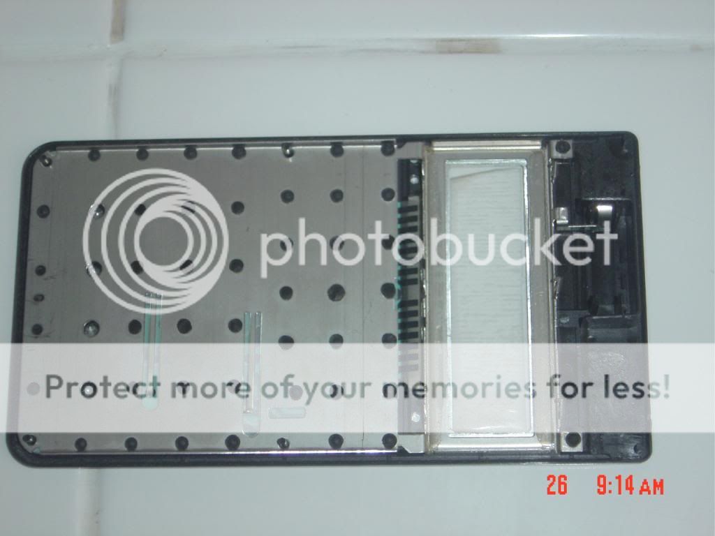
The picture shows the hole to fit an iPod connector. This would give accessed to the keyboard and external power as well ! Only the iPod connector had enough pins to do this. It took five days of spare time to the writer to cut the lower hole with a Stanley knife to fit perfectly and nicely the plug.
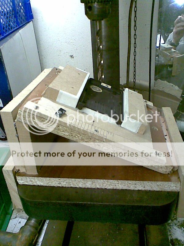
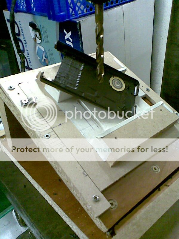
The d.i.y. tilted table used to cut space for the battery. It cuts half of the width, that is 1mm. The shell lays then on the battery itself. (The calculator is powered by its own cells)
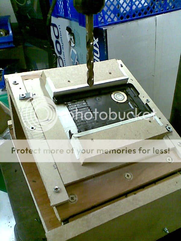
Carefully cutting of the shell took one hour and two people even thought the drill bit was new (sharp) it was not easy to cut.
Later on the surface was flattened with the Stanley knife.
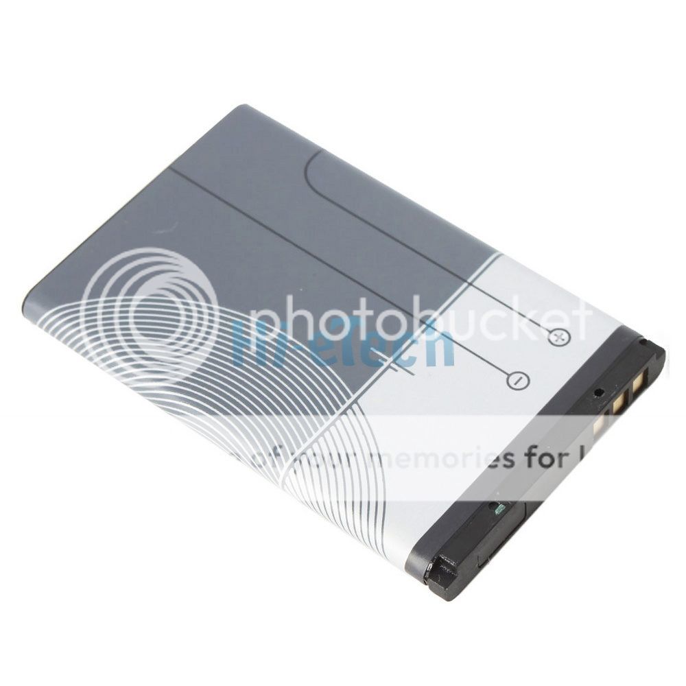
Nokia BL-4C. This battery is only 2mm thick:
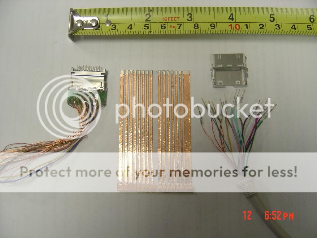
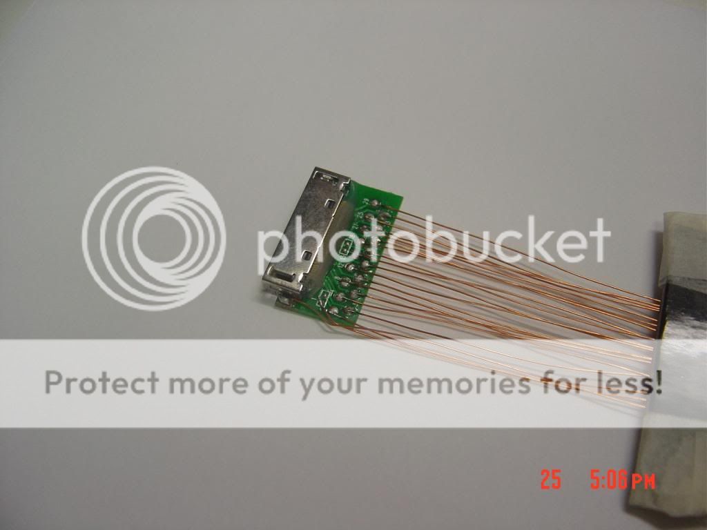
The core of the I/O port is this very small flexible printed circuit. It slides in between the mother board and the keyboard contacts. You can see the silver painted contacts on top. This was made with a plastic clear sheet and a cupper tape, then cutting slowly the copper to get the strips. The lower end has a very thing piece of wood to separate the copper from the plastic and be able to solder the contacts to the iPod connector. Everything is painted in clear varnish. The connector on the right is the male iPod. A second prototype of the flexible board was build. The left connector shows a very rough iPod plug to be tested on the HP17B, but not on the HP42EL (I wanted to make a removable memory chip on the HP17B with a small back up battery. This connector was very thin and with a lot of contacts for the chip, but that was another project)
This is the female connector. If you turn it upside down you can image it resting on the shell you have seen above. It fits perfectly.
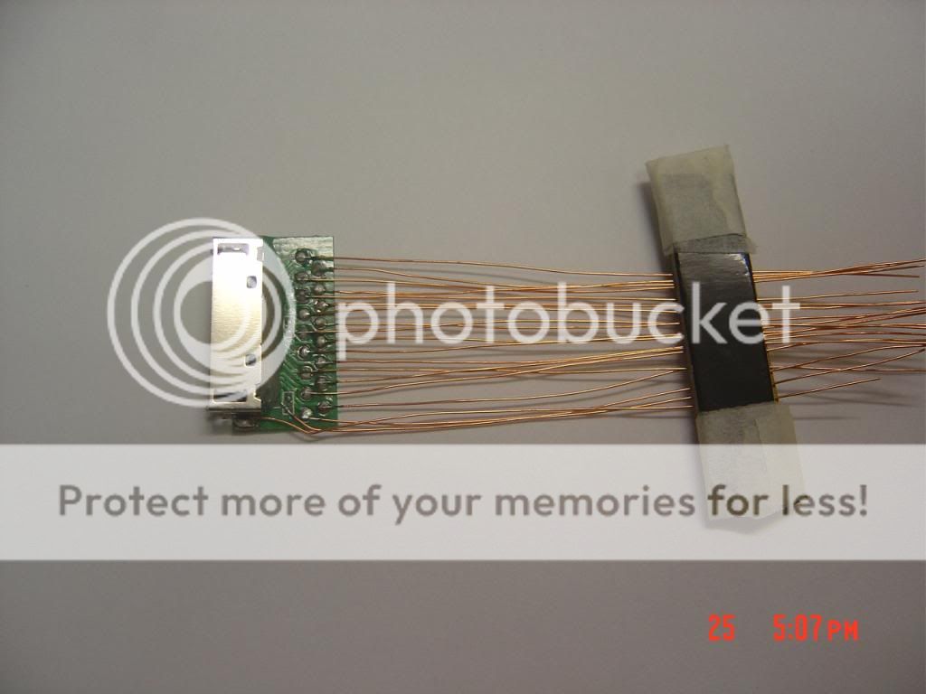
With some patient it was possible to use all plus one contact normally not used.
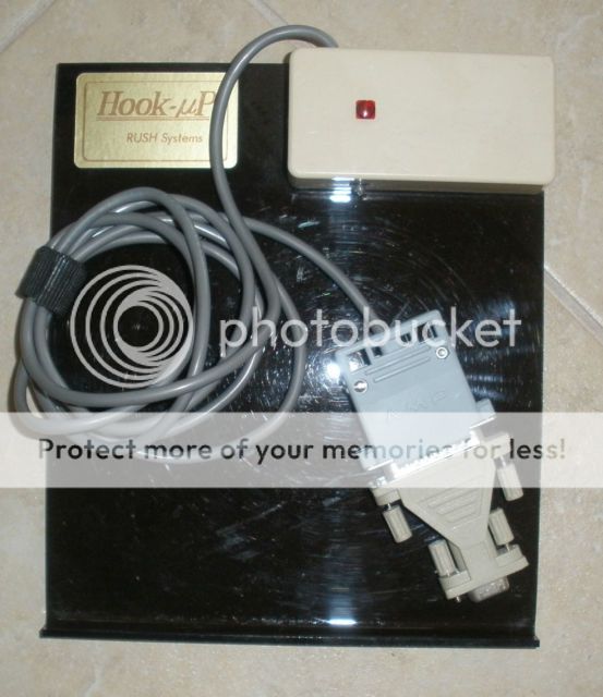
The project stopped here. The original Nokia 890mAh BL-4C battery gave a mediocre 1 hour runtime. I planned to make a docking station to run the power generator with an external battery. This would have given indefinitely running time really. The mayor problem was space and there was enough space to put a micro Nokia DC plug on the top. Alternatively the iPhone plug would provide power without the docking station but with a cable. The I/0 port would have used a circuit interface on the form of a box that just writes on the keyboard at high speed using the iPod connector and some programming code. Transferring data to the computer it is another story. This thing was listed as “transfer all your data to your computer. It uses DOS.....” It would be possible to use something like this, I only saw it once on sale, but I least it exist:
The original design had for objective to show that is was possible to pack an electroluminescent display and power source into the sleek design of a Pioneer. The I/O port was not included then, later on I had the idea of the flexible printed board and I thought it was easy to implement. So removing that from the head and with the exception of the black display we can say that there would have not been physical difference from this calculator and a normal one. It would have looked exactly the same ! Even the connector for the external AC in (the docking station) would have been hidden behind the battery port. However, the plastic shells could be taken apart by hand, and to give the case strength it would have been necessary to put four small screws. That would have ruined the design, and moved out from the original idea. But in fact it would have been unnecessary because the plastic shells fit tight one against each other as you know if you have taken apart one hp42s and put back the shells together. Anyway I don’t need the screws...at the end it is a prototype! I do like prototypes.
Jose Poyan