The Museum of HP Calculators

HP Forum Archive 21

[ Return to Index | Top of Index ]

Homemade ARM-based Calculator Programming Cable
Message #1 Posted by Katie Wasserman on 24 Aug 2012, 10:34 p.m.

I was able to make a fully functional programming cable to use for programming the ARM-based calculators (12C+, 15CLE, 10bii+, 20b/30b/wp34s). I made the 6-pin connector from scratch and used one of Harald Pott's USB converter boards (thank you Harald!). Furthermore I didn't need nor use HP's cable to mold, measure or even look at.

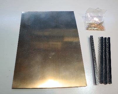
The basic materials are:

one of Harald's PCB's (is there a link to order them somewhere?)

0.8mm x 16.55mm spring loaded pins

2mm pitch x 2 row machine pin sockets

beryllium copper sheet 0.01" (.25mm) thick

some thin, stranded 6-conductor wire (ribbon cable is good)

some shrink wrap tubing

Here's how to make it:

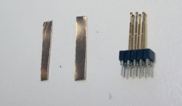
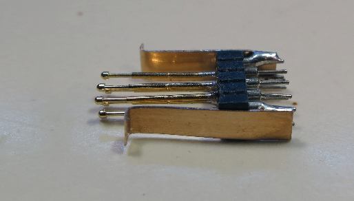
raw materials for connector:

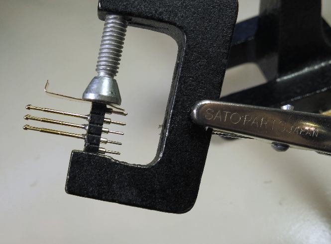
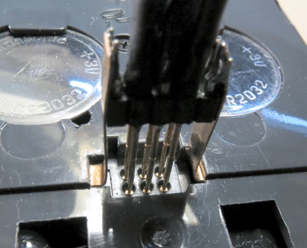
Cut a connector to get a 5-pin (x 2-pin) block. Cut the copper sheet to get two pieces: 3mm x 18mm and 4mm x 18mm. Insert 6 pins in the middle of the connector and solder them into place:

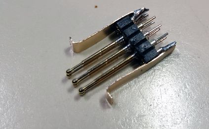
Make a small bend on the end of each piece of the copper that will serve as the hook to lock the connector in place. Solder the copper pieces in place as shown:

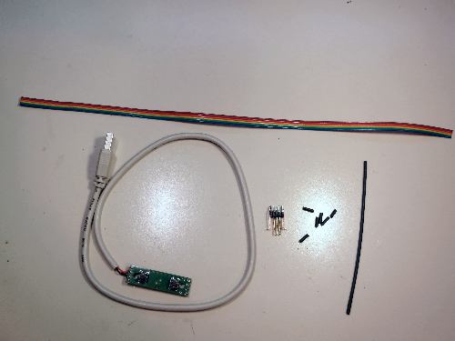
Here are the rest of the materials to finish the cable. Harald's cable comes with the USB wire and connector already attached. You need to add some standard size tact switches (for erase and reset). Any electronics distributor will have zillions of them to choose from:

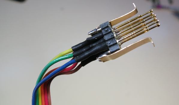
Now comes the hard part, soldering the wires to the back of the connector and to the PCB:

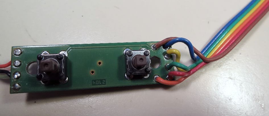
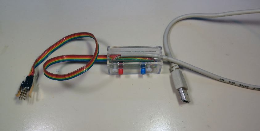
Here's the final cable with the board mounted in a little 1" x 2" Amac clear plastic box

Edited to remove an unnecessary and confusing comment

Edited: 25 Aug 2012, 12:12 a.m. after one or more responses were posted

      
Re: Homemade ARM-based Calculator Programming Cable
Message #2 Posted by Namir on 24 Aug 2012, 11:12 p.m.,
in response to message #1 by Katie Wasserman

I think you just won yourself a Nobel prize in physics!!!!

      
Re: Homemade ARM-based Calculator Programming Cable
Message #3 Posted by Paul Berger (Canada) on 24 Aug 2012, 11:18 p.m.,
in response to message #1 by Katie Wasserman

Very nice that is a very good idea you had for the clips, I was considering bringing the wire out the side and then use a one piece metal strap that went right over the top, but what you did looks a lot easier.

            
Re: Homemade ARM-based Calculator Programming Cable
Message #4 Posted by Katie Wasserman on 25 Aug 2012, 3:54 a.m.,
in response to message #3 by Paul Berger (Canada)

Paul,

The main thing that I concluded was that I had to use a 2mm pitch socket for the pins or I would have zero chance of aligning them properly. Once I had the socket in hand it just seemed logical to use it as the backbone of the plug.

The pins I used were the perfect diameter on both ends, but the connector would be a somewhat tighter fit if pins were shorter so that it wasn't so far away from the calculator. Did you find shorter pins to use?

                  
Re: Homemade ARM-based Calculator Programming Cable
Message #5 Posted by Paul Berger (Canada) on 25 Aug 2012, 1:23 p.m.,
in response to message #4 by Katie Wasserman

The ones I received are about 18mm so about the same as yours I think the only difference is mine are spear point. I wonder if the pins could be shortened? Another thing that comes to mind is you could drill through the bottom of the holes in the socket and then position the socket closer to the tip of the pogo pins and solder them in place and attach the wires to the ends of the pins protruding though the socket. You could also stabilize the pins by encasing them in something like hot glue or epoxy. I think epoxy putty would work good here but does not give you a lot of working time. Could you work shapelock in between the pins? I got some but have not tried to do anything with it yet.

                        
Re: Homemade ARM-based Calculator Programming Cable
Message #6 Posted by Katie Wasserman on 25 Aug 2012, 6:19 p.m.,
in response to message #5 by Paul Berger (Canada)

You can shorten the pins I have but only by a couple of millimeters. The internal spring runs most of the way through the sleeve and if you cut off too much it's toast. Soldering the pins into the socket keeps them pretty stable. It's just that the whole plug should be closer to the case so that it's easier to put the calculator down on a desk face up.

      
Re: Homemade ARM-based Calculator Programming Cable
Message #7 Posted by Walter B on 25 Aug 2012, 1:14 a.m.,
in response to message #1 by Katie Wasserman

Great work, Katie! And very well documented :-)

Now the inevitable dumb question applying to the WP 34S: Harald also offers a pcb with a USB port on it to be installed inside the HP-20b/-30b/WP 34s so you can use a standard micro USB cable for the computer link. Using this, the only additional thing required for programming would be your great 6-pin connector with pin J31 and J36 (reading J34 on the calculator board) shorted. This will replace the ERASE button. Kind of a programming dongle ;-) Correct?

      
Re: Homemade ARM-based Calculator Programming Cable
Message #8 Posted by Marcus von Cube, Germany on 25 Aug 2012, 3:16 a.m.,
in response to message #1 by Katie Wasserman

Very nice!

As Walter already pointed out, with the USB adapter installed, a simple short between the ERASE pin and +3V is enough for programming. A simple two pin version of the connector should be fine for this. I once did it with just a piece of wire. Once the WP34S firmware is up and running this trick is no longer needed except for recovery of a failed flashing attempt.

            
Re: Homemade ARM-based Calculator Programming Cable
Message #9 Posted by Katie Wasserman on 25 Aug 2012, 3:46 a.m.,
in response to message #8 by Marcus von Cube, Germany

Marcus and Walter,

If I had one of Harald's micro-USB boards installed in my 34s I would take things a step further and glue a small reed switch inside the case that's wired to Erase and +V. When you want to program you then just need a small neodymium magnet correctly placed on the outside of the case. This will cause the reed switch to connect Erase to +V while the magnet is in place.

I've used this "hidden switch" trick for several devices I've modded -- most recently an HP82240b printer that doubles as a recording device for a wireless thermometer. (I probably should write this up sometime.)

                  
Re: Homemade ARM-based Calculator Programming Cable
Message #10 Posted by rgray on 25 Aug 2012, 4:02 a.m.,
in response to message #9 by Katie Wasserman

Please do write up the remote recording thermometer project, Katie, I can't wait to see the details.

                        
Re: Homemade ARM-based Calculator Programming Cable
Message #11 Posted by Katie Wasserman on 25 Aug 2012, 7:33 p.m.,
in response to message #10 by rgray

I don't have much in the way of documentation on this as I just sort of slapped it together using pieces of code that I had worked on in other projects. I used a simple 433Mhz receiver like this one and hooked the output into a Parallax SX microcontroller.

The receiver picks up the signals sent by the Oregon Scientific remote temperature sensors (series 1) and the micro runs a program to decode these. (I use THR138 sensors). I figured this out myself based on some info found on the web, it was pretty tricky but fun to work out. Then the micro takes the temperature (in ASCII) and drives an IR LED with the correct encoding/timing that the HP82240A/B printer needs. The encoding/timing is well documented here.

I found that I could actually skip the IR LED and feed the modulation directly to the IR photo diode inside the IR printer. So I built a circuit into the printer and just use a little reed switch to activate it. It doesn't interfere with the normal function of the printer at all and the only external modification is the antenna wire hanging out of the back.

Here's the mostly uncommented code

Here's the really ugly mod in pictures:

Note the antenna and the little magnet on the HP name plate:

Here's reed switch glued under the nameplate and the ugly wiring:

and here's the dead-bug style microcontroller

and the RF module I used and located next to the paper roll:

Edited: 25 Aug 2012, 7:35 p.m.

                              
Re: Homemade ARM-based Calculator Programming Cable
Message #12 Posted by Dale Reed on 26 Aug 2012, 1:03 p.m.,
in response to message #11 by Katie Wasserman

Katie,

Many, many thanks for sharing the source. The comments are quite sufficient to be able to follow it, mostly because the routine names pretty well describe what each is doing. Using this beside the 82240 "Interfacing" manual makes it very clear.

Your pictures are also very helpful.

I have been wanting to make an RS-232 to 82240 IR widget to use for printing messages from a device that (still) has a serial port, and this should make it way easier. The only hard parts, for me, will be getting the timing exactly correct with the micro I'm using (MC9S08QG or similar) and figuring out a nice enclosure for it. (That'll be way easier if I can get enough current to power it from RTS and DTR... Then it might even fit in the hood on the D-shell connector with the IR LED sticking through the cable hole!)

Now I just need to find time to work on it. Maybe if I stopped typing long forum replies...

Dale

                                    
Re: Homemade ARM-based Calculator Programming Cable
Message #13 Posted by Katie Wasserman on 26 Aug 2012, 2:46 p.m.,
in response to message #12 by Dale Reed

I'm glad that the source code was readable and potentially useful to you. I found that the timing isn't as critical as "interfacing" manual says it is. Make sure that when you test your circuit the IR emitter is very close to the printer as you're likely to get less than 30cm distance from a couple of milliamps of current into the LED.

      
Re: Homemade ARM-based Calculator Programming Cable
Message #14 Posted by Harald on 25 Aug 2012, 5:58 p.m.,
in response to message #1 by Katie Wasserman

Hi Katie,

very nicely done! Thanks for sharing. I think this is probably most interesting for people who do not wish to modify their calculator with the USB board. Sorry there is no link for ordering the PCBs, just email to: h dot pott at gmx dot net. Originally the board was intended to replace the PCB in the HP cable, so the cable could directly be connected to the USB port without an RS232 adaptor. For that purpose it seemed best to reuse the original pushbutton - hence I don't have any of those right now. But if there is an interest in these boards I can order some buttons and maybe even make the connectors. Unfortunately I don't think I can buy beryllium copper in Germany.

Harald.

            
Re: Homemade ARM-based Calculator Programming Cable
Message #15 Posted by Katie Wasserman on 25 Aug 2012, 6:24 p.m.,
in response to message #14 by Harald

Quote:
Unfortunately I don't think I can buy beryllium copper in Germany.

This used to be easy to find in the USA, but not now. Is this becasue of ROHS, I really have no idea. However any sort of easy to cut, springy metal that can be soldered too will work. There's got to be something in a local hardware store that would do the trick.

                  
Re: Homemade ARM-based Calculator Programming Cable
Message #16 Posted by Walter B on 26 Aug 2012, 2:12 a.m.,
in response to message #15 by Katie Wasserman

Well, beryllium copper isn't really a healthy material due to the beryllium :-( But an arbitrary spring steel ("Federstahl") will do at least as well :-)

                        
Re: Homemade ARM-based Calculator Programming Cable
Message #17 Posted by Harald on 26 Aug 2012, 4:02 a.m.,
in response to message #16 by Walter B

Quote:
Well, beryllium copper isn't really a healthy material due to the beryllium :-(
I believe that is the reason why it has not been available here for many years.
Quote:
But an arbitrary spring steel ("Federstahl") will do at least as well :-)

Yes, that is true. But it is not as easy to cut, bend and solder as beryllium copper.

The pogo pins in the link aren't available to us Europeans either, but I am sure we can find an alternative there.

Edited: 26 Aug 2012, 4:05 a.m.

      
Re: Homemade ARM-based Calculator Programming Cable
Message #18 Posted by Dale Reed on 27 Aug 2012, 6:12 p.m.,
in response to message #1 by Katie Wasserman

Katie,

The only thing I would add is a couple plastic posts glued to one side of the "plug" to match the alignment slots on the calculator. Knowing me, I'd make the cable, then hook it up backwards and end up releasing the smoke from the most expensive component.

Dale

            
Re: Homemade ARM-based Calculator Programming Cable
Message #19 Posted by Katie Wasserman on 27 Aug 2012, 11:25 p.m.,
in response to message #18 by Dale Reed

I cut the beryllium-copper strips to different widths (3mm and 4mm) to match the notches for locking clips on each side of the connector. You can't put it on the wrong way!

The plug alignment slots are redundant, I'm not really sure why they are there. In fact, the 12C+ and 15CLE don't have them, they just have a space so that the same plug as used in the 20b/30b will fit.


[ Return to Index | Top of Index ]

Go back to the main exhibit hall