Re: 9114B Charger PCB Repair
Message #6 Posted by Tony Duell on 20 Sept 2008, 4:42 a.m.,
in response to message #5 by Egan Ford
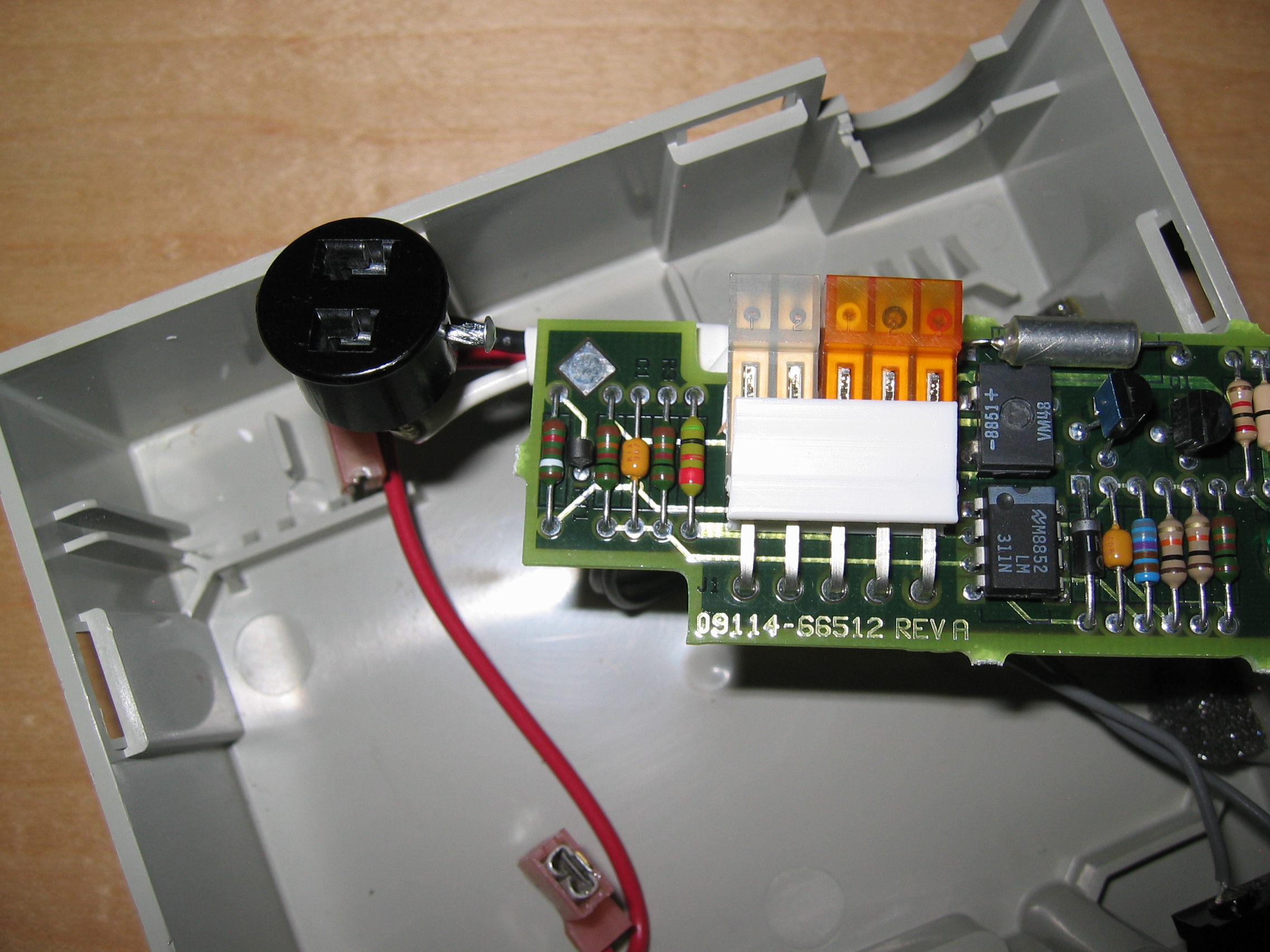
As far as I know all versions of the 9114 battery pack have a fuse on the charger PCB. On earlier models it's 2A, later ones are 5A. It's a little wire-ended 'Picofuse' and I think it's close to the 5 pin connector.
This is the only component between the battery and the 2 pin socket to the drive. If you're getting 6V at the battery and nothing at the drive then most likely that fuse has blown. Trace the connections to find it.
If the fuse has coloured bands rather than a printed value, read them like a resistor, but in _mA_. In other words green-black-red is 5000mA or 5A.
There are, indeed, 2 versions of the charger PCB. The one used in the -A battery (officially for the 9114A drive only) is a simple linear regulator. The one used in the -B battery (for all 9114s) is an SCR-based circuit IIRC. Schematics for both (and the rest of the 9114) are on the Australian site. That site has recently been modified and now has one of those infernal 'type in this munged word' anti-web-bot things :-(
| 