Some things can be done but you are limited due to the construction method...pics!
Message #5 Posted by Geoff Quickfall on 22 Mar 2008, 6:07 p.m.,
in response to message #4 by Eric Smith
Having restored 5 HP 01's to date all of them in non working and poor physical shape I can safely say there is a limited number of things one can do. This is due to the construction of the circuit boards and the way the were bonded together. So far this is a list of what can be checked followed by what can be done to the LED block:
1.  ensure the battery contacts are clean
2.  replace the quartz crystal as it is accessable.
3.  clean keyboard contacts, again because they are accessable.
4.  using silver trace paint corroded circuit traces can be reapplied on the battery side of the upper circuit board only
5.  some times the trimming capacitor fails and can be replaced.
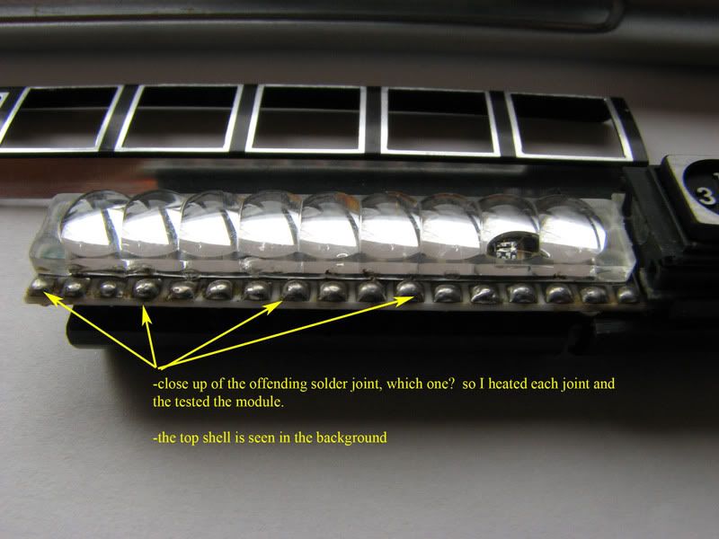
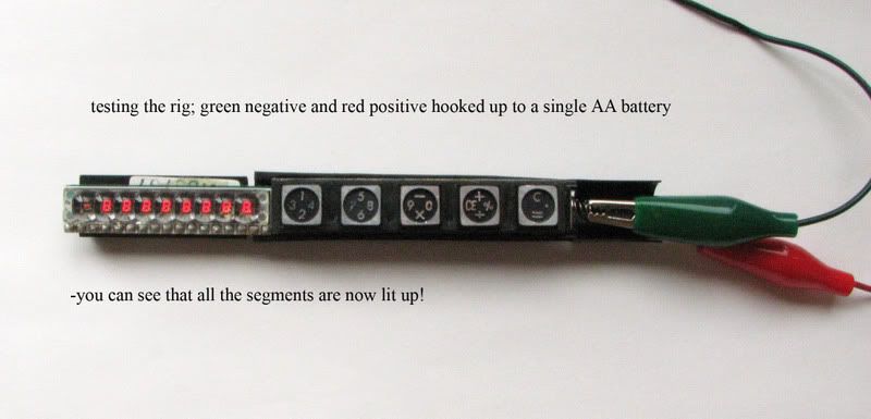
On specific LED failures sometimes resoldering the solder joints may actually fix a hidden cold solder problem. This can be done with the HP 01 and may solve your problem. I have successfully done this when the failure was with an entire row of similar segments on the HP and recently with a Calcupen:
The other failure with LED blocks is with the tiny wire bonds that come loose. On some exposed LED systems the wire bonds can be reattached via silver conduction epoxy as the wires are extremely fragile and tiny. I have done this under a stereo macroscope with success. Unfortunatley the HP 01 LED blocks are sealed under a led lense and this fix cannot be done.
Now some of the magic that can occur when trying to fix an HP module and LED display does involve gently heating and cooling the circuit board. You would only do this to a board that shows no other way to fix it. I have done this with PULSAR P2's and I think the affect, as it cannot be due to magic, is via expansion and contraction that has 'creeped' the offending circuit/wire bond back into place. Of course this is temporary fix at best but on fixiable watches it does tend to help track down the offending circuit which may be replaceable.
You should read up on your internals and here is a link to the HP Journal article, it will show you the modules construction and is very interesting. Pay particular attention to the pictures at the bottom of page 7 and you can see the solder joints I am refering to:
http://www.hp.com/hpinfo/abouthp/histnfacts/museum/personalsystems/0022/other/0022hpjournal.pdf
Here is a link to the cosmetic work I have also done to a beatup scratched up case and keyboard:
http://dwf.nu/viewtopic.php?t=2253&highlight=
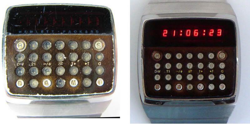
Before and after of the same watch:
Cheers, Geoff in Vancouver, Canada
Drop me an email as it MAY be fixable.
geoffqf@nospamtelus.net (of course remove the nospam!)
Edited: 22 Mar 2008, 6:23 p.m.
|