Re: HP 42S "Input Project"
Message #1 Posted by Paul Brogger on 17 Apr 2003, 9:52 a.m.
I think you'll find somewhere in the Archives a series of posts on "The INPUT Project" . . .
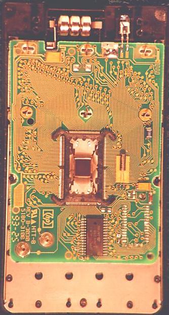
I wired a ribbon cable to an HP-17B circuit board -- one line for each trace in the keyboard matrix. It wasn't long before I discovered that by connecting a row and column wire through a resistor (not shorting them directly), I could simulate keypresses. The circuit board with the gray ribbon cable and lots of bare wire ends is still in my calculator fix-it box. (I'll donate it to the Museum if it's ever of historical interest. ;^) ) By identifying the proper traces, it is possible to gain access to all of the keyboard traces from the exposed side of the PCB -- no disassembly is required beyond opening the back case.
I thought in terms of an array of magnetic relays, spaced about a flex circuit which would be laid inside the back case of the calculator, and then either wired to the circuit board (no PCB/LCD disassembly required) or inserted into the PCB/keyboard connector (PCB/LCD disassembly necessary). With a few more draws on the hookah, I could imagine a little tray with an IR sensor in the top end, and a matching array of electromagnets in the base, all tied to the PC (or an HP-48) through a serial or parallel connector . . .
With such an arrangement, one could simply set the HP-42s in its "docking station", launch some fancy interface software on the PC, and go have dinner. The PC should be able to wake up the 42s, verify the keyswitches are working, download any data calculated or input, delete anything requiring deleting, and then enter programs as specified. By the time the dishes were done (or maybe the next morning), the 42s should be ready to roll . . .
I think such a thing is doable -- but my electronics design and interfacing abilities are not even rudimentary. (My choice of magnetic relays probably betrays my seriously out-of-date design toolkit!) Of course, the magnetic relay approach needn't necessarily be taken. One could simply insert some sort of micro-fine edge connector such as is found in PDAs, or hang a gray ribbon cable with a DB-25 or smaller thingie on it. This would involve exposing the 42s' CPU leads directly and permanently to the outside world, and I'm not sure how good an idea that is. Another approach might involve optoisoloators and a simple power connection, that might even be separate from the 42s' power lines.
Someone else was going to look into using semiconductor switches to simulate the keypresses, but I haven't heard an update, and don't think anything is being actively pursued.
The effort of embarking upon such an undertaking needs to be balanced against the perceived gain over what is already available. The HP-48G is unfortunately bigger and clunkier, and the RPL vs. RPN drawback is significant for some, and the later vintage of its manufacture has resulted in a less satisfying look and feel, and . . .
But the '48 has a lot going for it, and there are PDA's available too. I know they aren't an HP-42S, and an emulator running on a PDA is but a sterile, barely tantalizing reminder of the original device. But just how much is, say, the difference between an HP-48 and an HP-42s worth?
Maybe enough to organize a 42s Input Project, maybe not.
| 