![]() The Museum of HP Calculators
The Museum of HP Calculators
This modification should be attempted only by people with experience working with delicate electronic circuits. It is quite possible to damage your calculator during this modification. Observe static precautions and beware of heat damage. If you find any errors, please contact the curator.
This information is supplied without representation or warranty of any kind. The Museum of HP Calculators does not assume any responsibility and shall have no liability, consequential or otherwise, of any kind arising from the use of this information.
The HP-45 had an undocumented timer feature which was relatively inaccurate due to the lack of a crystal. This modification adds a 784 kHz crystal (and possibly a resistor) to improve accuracy.
Remove two screws from inside the battery compartment, two from under the bottom feet and two from under the upper corners of the large rear label. (The corners of the label can be carefully peeled back and replaced but it won't look brand new.)
With the back removed, remove the eight screws that hold the backbone to the front case. Carefully remove the backbone and circuit boards while holding the calculator face down to prevent the keys from falling out. The power switch may stay with the front case or stick to the circuit board.

Remove the CPU circuit board from the keypad/display board by gently pulling it up off the pins and set it aside. Once this circuit is removed, the only things holding the backbone to the keypad/display board are the power supply wires. You can either leave them attached and rotate the backbone out of the way or desolder them.
When you turn the keypad/display board over, the top will look like:
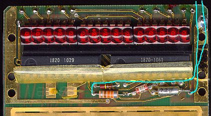
The light blue lines represent wires you will add.
The detail above shows a 330 uH choke that you should remove. Attach insulated wires from the crystal to the points shown above. The wires should be long enough to allow tucking the crystal behind the circuit board above and behind the LEDs. (Wrap the crystal in electrical tape to insulate it.)
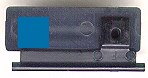
You may also wish to glue a small piece of plastic to the back of the ENTER key such that ENTER presses both key contacts when depressed. With this modification you can press RCL and then ENTER instead of RCL and then CHS-7-8 (at the same time) to enter timer mode. This bit of plastic is shown in blue on the back of the ENTER key below.
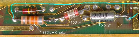
If everything works, you're done. If it doesn't work reliably you can try using the choke you removed and a new resistor to form a circuit like:
Try resistors in the range of 1K-100K ohms until you get reliable operation.